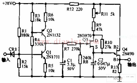
The control circuit of the step servo is shown in the figure below. This circuit uses a variable single-junction transistor oscillator to generate a pulse train under the control of digital level. A logic level of 1 produces 1000 pulses per second; a logic level of 0 produces 4400 pulses per second. When the logic level changes, the transition between the two pulse rates is smooth. The pulse train is used to start the stepper servo motor. Q1 and Q2 are two constant current sources, and Q3 is used as a voltage controlled resistor in parallel with R10 to control the pulse train speed of the single junction transistor oscillator. ShenZhen Antenk Electronics Co,Ltd , https://www.coincellholder.com
