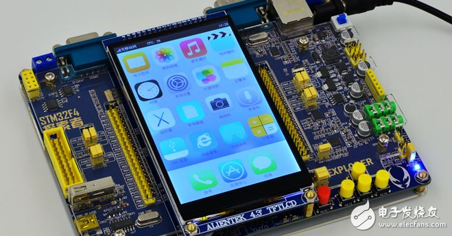
Independent watchdog (IWDG) and low-power mode are often used in STM32 development. The watchdog is designed to detect and resolve faults caused by software errors. The low-power mode is for entering when the CPU does not need to continue running. To sleep mode to save power. The independent watchdog clock is provided by an independent RC oscillator (typically 40kHz for STM32F10x) and is still valid even if the master clock fails. Therefore, it can operate in stop and standby modes. And once the independent watchdog starts, it cannot be stopped except for a system reset. However, a problem caused by this is that when the MCU enters the low-power mode, the dog cannot be fed due to the CPU stopping operation, which may cause the system to be frequently reset. How to solve this problem? Can independent watchdog and low-power mode be used together? A good way is to feed the dog in sleep mode with the RTC wake-up at a regular time, feed it enough to continue entering sleep mode. For example, the watchdog reset interval is 10s. Then set the RTC alarm interrupt time to 5s before entering sleep mode. In this way, the dog is fed once every 5s. This can be a good solution to this problem. While(1) { // Execute the task Task1(); Task2(); //.. // feed the dog Dev_iwdg_feed(); // Enter standby mode switch If(m_bEnterStandByMode) { // Enable external interrupt, GPIOB3, to wake the MCU from standby mode dev_exTI_enable(TRUE); ENTERSTOPMODE: // Set RTC alarm, generate RTC alarm interrupt in 5 seconds */ dev_rtc_setAlarm(5); // Enter stop mode (low power consumption) until wake-up triggered by external interrupt PWR_EnterSTOPMode(PWR_Regulator_LowPower, PWR_STOPEntry_WFI); // Whether it is an RTC alarm interrupt If(dev_rtc_isAlarm()) { // feed the dog Dev_iwdg_feed(); // Feeding the dog continues into stop mode Goto ENTERSTOPMODE; } // Disable external interrupts dev_exTI_enable(FALSE); // Resume system clock after wake-up from stop mode Dev_clk_restore(); } } The following is the complete code: //************************************************ ********************************************** // STM32F10x StopMode RTC Feed Dog // compiler: Keil UV3 // 2013-01-04 , By friehood //************************************************ ********************************************** #include "stm32f10x_lib.h" #include "platform_config.h" staTIc Boolean g_bRTCAlarm = FALSE; /************************************************* ****************************** * FuncTIon Name : RCC_Configuration * Description : Configures the different system clocks. * Input : None * Output : None * Return : None ************************************************** *****************************/ Void RCC_Configuration(void) { /* RCC system reset(for debug purpose) */ RCC_DeInit(); /* Enable HSE */ RCC_HSEConfig(RCC_HSE_ON); /* Wait till HSE is ready */ If(RCC_WaitForHSEStartUp() == SUCCESS) { /* Enable Prefetch Buffer */ FLASH_PrefetchBufferCmd(FLASH_PrefetchBuffer_Enable); //Flash timing control //Recommended value: SYSCLK = 0~24MHz Latency=0 // SYSCLK = 24~48MHz Latency=1 // SYSCLK = 48~72MHz Latency=2 //FLASH_SetLatency(FLASH_Latency_1); //Warning: Changing to 1 will have an effect on the DMA value (if the ADC acquisition value will be misaligned) FLASH_SetLatency(FLASH_Latency_2); /* HCLK = SYSCLK */ RCC_HCLKConfig(RCC_SYSCLK_Div1); /* PCLK2 = HCLK */ RCC_PCLK2Config(RCC_HCLK_Div1); /* PCLK1 = HCLK/2 */ RCC_PCLK1Config(RCC_HCLK_Div2); /* PLLCLK = 12MHz * 3 = 36 MHz */ RCC_PLLConfig(RCC_PLLSource_HSE_Div1, RCC_PLLMul_3); /* Enable PLL */ RCC_PLLCmd(ENABLE); /* Wait till PLL is ready */ While(RCC_GetFlagStatus(RCC_FLAG_PLLRDY) == RESET) { } /* Select PLL as system clock source */ RCC_SYSCLKConfig(RCC_SYSCLKSource_PLLCLK); /* Wait till PLL is used as system clock source */ While(RCC_GetSYSCLKSource() != 0x08) { } } /* Enable PWR and BKP clock */ RCC_APB1PeriphClockCmd(RCC_APB1Periph_PWR | RCC_APB1Periph_BKP, ENABLE); /* Enable AFIO clock */ RCC_APB2PeriphClockCmd(RCC_APB2Periph_AFIO, ENABLE); } /************************************************* ****************************** * Function Name : NVIC_Configuration * Description : Configures the nested vectored interrupt controller. * Input : None * Output : None * Return : None ************************************************** *****************************/ Void NVIC_Configuration(void) { NVIC_InitTypeDef NVIC_InitStructure; #ifdef VECT_TAB_RAM /* Set the Vector Table base location at 0x20000000 */ NVIC_SetVectorTable(NVIC_VectTab_RAM, 0x0); #else /* VECT_TAB_FLASH */ /* Set the Vector Table base location at 0x08000000 */ NVIC_SetVectorTable(NVIC_VectTab_FLASH, 0x0); #endif /* Configure one bit for preemption priority */ NVIC_PriorityGroupConfig(NVIC_PriorityGroup_1); } /************************************************* ****************************** * Function Name : SysTick_Configuration * Description : Configures the SysTick to generate an interrupt each 1 millisecond. * Input : None * Output : None * Return : None ************************************************** *****************************/ Void SysTick_Configuration(void) { /* Select AHB clock(HCLK) as SysTick clock source */ SysTick_CLKSourceConfig(SysTick_CLKSource_HCLK); /* Set SysTick Priority to 3 */ NVIC_SystemHandlerPriorityConfig(SystemHandler_SysTick, 3, 0); /* SysTick interrupt each 1ms with HCLK equal to 72MHz */ SysTick_SetReload(72000); /* Enable the SysTick Interrupt */ SysTick_ITConfig(ENABLE); } /************************************************* ****************************** * Function Name : Delay * Description : Inserts a delay time. * Input : nTime: specifies the delay time length, in milliseconds. * Output : None * Return : None ************************************************** *****************************/ Void Delay(u32 nTime) { /* Enable the SysTick Counter */ SysTick_CounterCmd(SysTick_Counter_Enable); TimingDelay = nTime; While(TimingDelay != 0); /* Disable the SysTick Counter */ SysTick_CounterCmd(SysTick_Counter_Disable); /* Clear the SysTick Counter */ SysTick_CounterCmd(SysTick_Counter_Clear); } /************************************************* ****************************** * Function Name : RTC_Configuration * Description : Configures RTC clock source and prescaler. * Input : None * Output : None * Re Electric Vehicle Battery Supply Lithium-Ion Batteries Electric Vehicle Supply Chain,Electric Car Supply Chain,Supply Chain For Electric Vehicle Batteries,Materials For Ev Battery Shenzhen Zhifu New Energy Co., Ltd. , https://www.sunbeambattery.com
Lithium-ion batteries are currently used in most portable consumer electronics such as cell phones and laptops because of their high energy per unit mass relative to other electrical energy storage systems. They also have a high power-to-weight ratio, high energy efficiency, good high-temperature performance, and low self-discharge. Most components of lithium-ion batteries can be recycled, but the cost of material recovery remains a challenge for the industry. The U.S. Department of Energy is also supporting the Lithium-Ion Battery Recycling Prize to identify solutions for collecting, sorting, storing, and transporting spent and discarded lithium-ion batteries for eventual recycling and materials recovery. Most of today's PHEVs and EVs use lithium-ion batteries, though the exact chemistry often varies from that of consumer electronics batteries. Research and development are ongoing to reduce their relatively high cost, extend their useful life, and address safety concerns in regard to overheating.