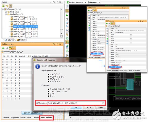
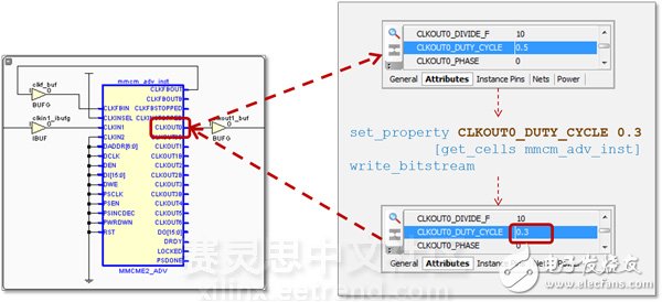
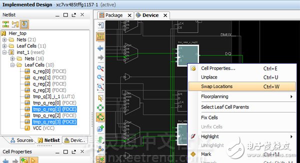
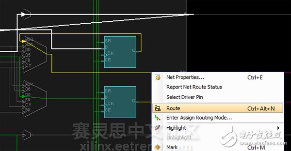
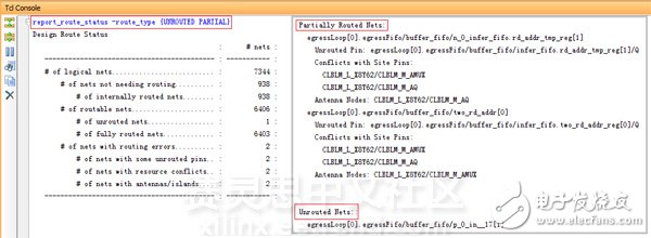
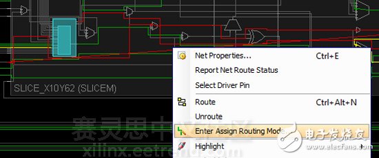
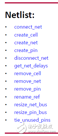
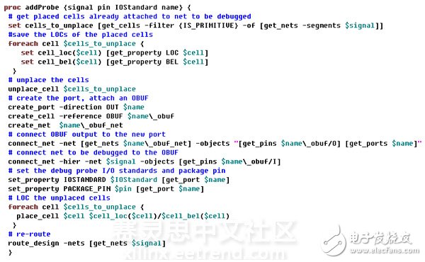
About Tcl's application in Vivado From the basic syntax of Tcl and the application in Vivado, following the previous article "Customizing Vivado Design Implementation Process with Tcl", it introduces how to extend or even customize the FPGA design implementation process, which leads to a more Details of the application scenario: how to use Tcl to partially edit the netlist or place and route on the finished layout design, so as to complete the individual design change requirements in the shortest time and at the least cost. What is ECO ECO refers to the Engineering Change Order, the engineering change order. The goal is to make small-scale modifications quickly and flexibly at the end of the design to maintain the verified functionality and timing as much as possible. The name of ECO is inherited from the field of IC design. Its application is the first time in FPGA design, but this practice has been widely adopted in the past FPGA design. Simply put, ECO is equivalent to the FPGA Editor on ISE. But unlike the FPGA Editor, the ECO in Vivado is not a stand-alone interface or a specific command. Different ways to implement different ECO functions are required. ECO application scenario and implementation process The application scenarios of ECO mainly include: modifying cell attributes, adding or subtracting or moving cells, and manual local wiring. There are also complex scenarios that require multiple operations, such as putting the RAM (or DSP) output registers into/out of RAMB (or DSP48), or connecting the design internal signals to I/O for debugging purposes. and many more. The ECO implementations supported in Vivado are slightly different for different application scenarios. Some can be implemented using a graphical interface, while others can only use Tcl commands. However, operations that can usually be implemented on a graphical interface can be implemented using one or more Tcl commands. The implementation process of ECO is shown in the following figure: The design referred to in the first step is usually a fully laid-out design. If it is in engineering mode, you can open the implemented design directly in the IDE. If there is only DCP file, whether it is engineering mode or non-engineering mode. DCP can be opened with the open_checkpoint command. The second step is the meaning of ECO. We perform various operations on the layout and layout design, and then only partially layout/route the changed parts without the need for the overall re-run design, saving a lot of time without destroying the already The timing of the convergence. The third step is to generate the bit file for download. In this case, you must directly enter the command in the Tcl Console or Tcl mode to generate the bit file, instead of using the "Generate Bitstream" button on the IDE. The reason is that the latter read the original design of the place and route before ECO, and the generated bit file is naturally unusable. Modify attribute Most of the property changes can be done through the IDE interface, as shown below: For example, to modify the initial value of the register INIT or the truth table of the LUT, the user only needs to open the layout design (Implemented Design) in the Vivado IDE, find and select the FF/LUT in the Device View, and then on the left. In the Cell ProperTIes view on the side, select the attributes that need to be modified and modify them directly. In addition to the operation of the FF/LUT, many times we need to modify the phase shift of the MMCM/PLL output clock. For this application, the user does not need to regenerate the MMCM/PLL. Similar to the above method, it can be directly modified on the Device View after layout. Mobile/exchange cells Mobile/switched cells are the most basic scenario for ECO operations on FF/LUTs, and only this can be done graphically. If you want to delete cells, you can only use the Tcl command. The specific operation method is also quite simple. To swap the positions of the cells, just select the two cells you need on the Device View, two FFs as shown above, then right-click the menu and select Swap LocaTIons. To move cells is simpler, just drag FF to the new location in the figure. When the user moves or changes the position of the cells, they will find that the nets connected to them are highlighted in yellow, indicating that these nets need to be rerouted. What needs to be done at this time is to select these nets in the figure and then right-click to bring up the menu and select Route for local routing. After local wiring, be sure to check the wiring in the Tcl Console using the report_route_status command to ensure that there are no unrouted (unrouted) or partially unfinished (parTIal routed) nets. Adding options to this command will report more detailed results, as shown in the following figure. If you change the slightly more complicated Tcl command with the graphical display, it is more intuitive, and it is also convenient to right-click the command to perform targeted local wiring. Manual wiring Manual routing is an unconventional way of routing, which can only be performed on a single screen in a graphical interface. The so-called manual routing, in addition to the manual selection of one node and one node, also supports the tool to automatically select resources for wiring. Usually we don't recommend a full manual approach. Vivado is a timing-driven tool, so its automatically selected routing results are already the best choice for timing constraints. In the Device View, select a net that is not wired or pre-unrouted (displayed in red highlighting), right-click the menu and select Enter Assign RouTIng Mode... to enter manual routing mode. Complex ECO scene More than half of the length, has been paving the way, in fact, the most practical ECO has not been mentioned. I believe that most users miss the function of FPGA Editor is probe, how to quickly connect an internal signal to the FPGA pin, without re-layout, directly update the bit file and download and debug. I have been asked many times by customers, and many people deeply regret that Vivado does not support such an approach. In fact, such a similar function has been supported in Vivado. The only problem is that there is no graphical interface for one-click operation (the development work is already underway). But thanks to the flexibility of Tcl, we can implement the probe function more specifically, and the efficiency is higher. Tcl operation command In UG835, Vivado-supported Tcl commands are classified according to Category. The commands listed in the Netlist directory are those that are needed to implement ECO. The ECO, which usually involves adding or subtracting cells, is basically a three-step implementation: first create the relevant cell and / or net with create_cell / create_net, and then use the disconnect_net / connect_net command to correct the connection caused by the cell and net changes. Finally, use the route_design plus option to complete the local wiring. Different Vivado versions have slightly different restrictions on such ECO modifications. For example, in the version after 2014.1, the cell needs to be released from the current layout position by unplace_cell before changing the connection relationship of the cell, and the new connection relationship is completed. Then, use place_cell to put it in the new layout position. The specific operation can change the specific Tcl command according to Vivado's prompt or error message, but the operation idea and the available commands are almost the same. This is a Tcl script that implements the probe function on Vivaod. It has been written as a proc subroutine and is easy to understand. Can be called directly, or can be made into Vivado's embedded extension commands. To call the generator, just source the script first, then type the command in the Tcl Console as shown below. The script has been tested on Vivado 2014.3 and 2014.4. Only one probe can be added at a time, and the signal name, pin location, level standard and probe name must be entered in the above order. Because you do not have the preflight function, you may encounter some error messages and you will not be able to continue. For example, if the selected signal is only present in the INTRASITE inside the SLICE, it cannot be pulled out to the pin. For example, if you type the command and misspelled the level standard, it will cause the Tcl to partially modify the Vivado database and cannot continue. At this point, you can only close the DCP that has already been opened and choose to go back without saving. Users can extend this Tcl script according to their needs, or follow the Tcl method to achieve other ECO requirements. For example, the article begins with an example of a scene in which the FF of the RAMB output level is pulled out onto the fabric. The basic implementation method and idea are similar: first change the attribute of the RAMB output port REG to 0, and then create a The new FF, connect its input to the output of RAMB, and then connect the output of FF to the cell driven by the original RAMB output, and complete the correct connection between the clock and reset terminal of FF, then select the appropriate position to place the new FF, and finally For the newly added nets local wiring. It can be seen that the ECO implemented by Tcl is not as simple and intuitive as the graphical interface, but it gives the user maximum freedom. It is entirely up to the user to decide how to modify the design, even if the result of the layout and timing closure has been completed, it can directly change the connection relationship of the underlying units, or even increase or decrease the design. ECO's development on Vivado After more than two years of development, there have been many ways to implement ECO on Vivado, in addition to the techniques available in the aforementioned graphics, as well as user-defined Tcl commands and scripts. With the launch of the Xilinx Tcl Store, users can download and use Tcl scripts like downloading apps in the App Store, simplifying the application of Tcl on Vivado and further extending the in-depth and refined use of Tcl, including Tcl in Application on ECO. A lot of useful scripts have been added to Vivado 2014.4. Once you have installed Vivado, just open the Tcl Store, find Debug Utilities, click Install, and wait a moment to see an add_probe Tcl proc installed into your Vivado. The add_probe is extended based on the addProbe example above, not only to add a probe, but also to change the signal of the existing probe connection. In addition, this script uses the argument method, click on the program to see help, so you do not have to input the signal, level standards and other options in order, there is no problem with the wrong input. In addition, the pre-check and error correction functions have been added. If the problem is encountered, the error will be exited without changing the Vivado database, which is more efficient. In addition, there are many other useful scripts on the Tcl Store. You are welcome to try and give us feedback. Although there are very few scripts about ECO, we have been adding. In addition, Tcl Store is a completely open source environment based on GitHub. Of course, you are welcome to upload your own useful Tcl scripts to supplement them. In general, ECO is a relatively large proposition because it involves too many changes, but it is also difficult to limit it to a GUI interface. The purpose of this article is to let everyone have a basic understanding of the realization of ECO on FPGA, combing the seemingly complex and disorderly process, the so-called view of a leaf and know the autumn, glimpse and see the whole leopard, hope to bring more User confidence, it is not difficult to use Vivado. Single Phase Control Transformer Main components
5. Product insulation grade: Class B III.
Environmental conditions editing broadcast Single Phase Control Transformer,Control Transformer,Isolation Control Transformer,Machine Tool Control Transformer Henan New Electric Power Co.,Ltd. , https://www.newelectricpower.com


Vivado% addProbe inst_1/tmp_q[3] D9 LVCMOS18 my_probe_1 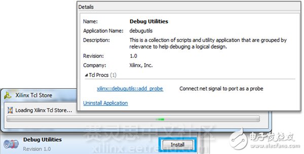
This product is made of high-strength enamelled wire and high-quality silicon steel sheet. BK series transformer core is shell type, which is laminated by silicon steel sheets; BKC series iron core is C-core type.
Technical characteristics
1. BK, BKC and other series of control transformers (hereinafter referred to as transformers) are applicable to power supply for local lighting in industrial and mining enterprises, power supply for control circuits in electrical equipment, and power supply for signal lights and indicator lights in circuits with AC 50Hz~60Hz and voltage up to 500V.
2. The transformer can work for a long time under rated load.
3. The primary and secondary windings of the transformer are separated. When the secondary has only one winding, it bears all the rated capacity of the transformer. If the secondary has both control, lighting and indicator windings, it is wound separately according to the distribution of winding capacity. For the transformer with single winding and intermediate tap, the capacity of each intermediate tap is less than the rated capacity of the transformer, and only the maximum voltage output terminal can bear the rated capacity.
4. The product meets the standard: GB19212.3-2006.
1. The ambient air humidity is - 5 ℃ to+40 ℃, and the 24-hour average value shall not exceed+35 ℃;
2. The altitude of the installation site shall not exceed 2000 meters;
3. The relative humidity of the atmosphere shall not exceed 50% when the ambient air humidity is+40 ℃. There can be a higher relative humidity at a lower temperature. The average maximum humidity of the wettest month is 90%, and the average minimum temperature of the month is+25 ℃. In addition, the condensation on the product surface due to temperature changes shall be considered.
4. Places without violent vibration and impact vibration;
5. A place protected from rain and snow;
6. The voltage waveform is approximately sine wave.