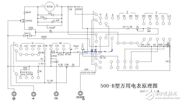
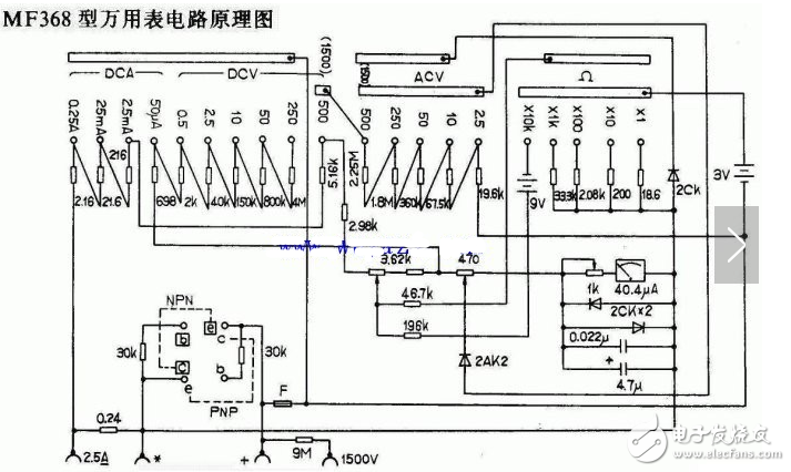
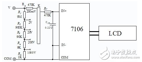
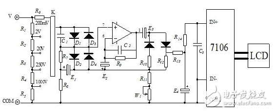
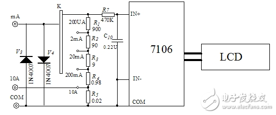
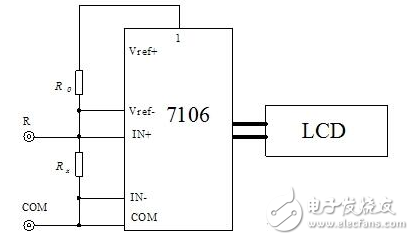
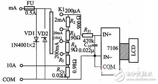
The digital multimeter is based on a DC digital voltmeter with only a basic range. This voltmeter is equivalent to the "header" of a digital multimeter. The principle is shown in Figure 1. In Figure 1, except for the display, all the functions can be integrated on one chip. The chip with these functions is called A/D converter. The more common ones are ICL7106, ICL7107 and other models. They belong to double integral type A. /D converter. Although the internal circuit of the dual-integration A/D converter is complicated, the circuit according to Fig. 1 can explain the principle. Its working process in a measurement cycle is as follows: At the beginning of the test, the counter is cleared, the integral capacitor c is discharged, then the control logic turns K2 and K3 off, K1 is turned on, the integrator positively integrates the measured voltage Vx, the forward integration is also called sampling, and the integral output V01 during the sampling period. The linearity increases, and the zero-crossing comparator obtains the zero-crossing square wave. When the gate G is opened by the control logic, the counter starts counting the clock pulse. When the highest bit is counted to 1, the overflow pulse is disconnected by the control logic to make K1 and K3, K2 is connected. Pass, the sampling ends, and the counter is reset to zero. Set the sampling process time to T1, then the integral output V01=VxT1/RC......(1). After K2 turns on the reference voltage VR, the integrator starts the second integration (reverse integration), V01 starts to decrease linearly, and the counter also restarts. count. When V01 drops to zero, the negative square wave of the comparator output ends, the control logic turns K2 off, K3 turns on, and the integration stops. At the same time, the door G is closed, the counting is stopped, and one measuring cycle ends. Let the reverse integration process time be T2, then the integral output is V01-VrT2/RC=0 (2). From the equations (1) and (2), Vx = VrT2 / T1 (3) can be obtained. The conversion waveform is shown in Figure 2. Let the clock period be T0, then T1=N1T0, T2=N2T0, N1 and N2 are the number of clock pulses counted during the forward and reverse integration, respectively, so VX=VRN2/N1...(4). For the dry 31/2-bit A/D converter, the counter overflows when counting up to 1000 pulses during sampling, so N1=1000 is a fixed value. If VR=100.0mV is specified, then VX=0.1N2......(5 ). (5) The description shows that by appropriately selecting the values ​​of N1 and VR, the effective numbers of VX and N2 can be made the same, except that the decimal point position is different. If the decimal point is set to the tenth position of the display value N2, it can be directly read. For example, if VX=123.4mV is measured, then when N2=1234 pulses are counted during reverse integration, one measurement period ends, and the display should display 1234, but a decimal point appears before the digits on the circuit, so the actual display 123.4. The temporarily stored N2 value in the counter is a binary number, which can be decoded by the decoder to enable the digital display to display a decimal number. As can be seen from the above formula (4), the allowable range of VX is related to the size of VR. For a 31/2-bit A/D converter, if VR = 100.00mV, the maximum display is 199.9mV; if VR = 1.0V, the maximum display is 1.999V. In fact, VR should not be too large, otherwise it will damage the A/D converter. For example, if VR=100.0mV, the 31/2-bit A/D converter can form a DC digital voltmeter with a basic range of 0.2v. Many popular digital multimeters are extended with this DC digital voltmeter with a basic range of 0.2v. To measure a higher DC voltage, a voltage divider can be used to reduce the measured voltage to less than 0.2V. To measure AC voltage, AC, DC current and resistance, you can use a corresponding converter to convert to DC voltage. If the measured electric quantity is large, it can be divided (or shunted) and then converted, so that the converted DC voltage is below 0.2V. The block diagram of the digital multimeter is shown in Figure 3. From the working process of the double integral A/D converter, the characteristics of the digital multimeter can also be seen: First, from the above formula (4), the measured voltage is only related to the reference voltage and the counter value, and the two are accurate. The degree can be made higher, so the digital multimeter test has higher accuracy. Second, the short-term interference superimposed on the VX is integrated during the integration process. If T1 is the value of the power frequency signal (integer multiple of 20ms), the power frequency interference superimposed on the VX will be integrated, so its resistance to serial mode interference is strong. Third, the resolution is high, and the highest resolution of the 31/2 digit digital multimeter is 0.1 mV. However, it also has shortcomings. From the working process of the double-integral A/D converter, if VX is a variable amount, the forward and reverse integrals and the counter count cannot be performed normally, and the display will be disordered, so the digital multimeter cannot measure continuously. The amount of electricity. A multimeter is a meter used to measure AC and DC voltage, resistance, DC current, and the like. It is an indispensable tool for electrician and radio production. At first glance, the multimeter is very complicated. In fact, it is similar to the DC voltage measured by the ammeter (commonly known as the meter), the dial, the probe, and the measuring resistor. Only a set of batteries must be added during the test. When the selector switch points to the resistance range, the first row of resistance-specific scale readings can be found on the dial. The digital measurement converts some measurement signals into DC voltage signals, which are then converted into digital signals by an analog-to-digital conversion circuit, then counted by a counter, and finally the measurement results are directly displayed by numbers. It can measure DC voltage, AC voltage, DC current, AC current and resistance, as well as parameters such as frequency, capacity, and amplification. It also has automatic zero calibration, automatic polarity switching, overload indication, and hold reading. , display the measurement unit symbol and other functions. The system block diagram. The digital multimeter system block diagram, as shown: The DT830 multimeter uses a large-scale integrated chip 7106 (or 7107) as the analog-to-digital conversion circuit and display driver circuit of the circuit. The pin functions are as follows. (1) DC voltage measurement circuit DC voltage circuit schematic, as shown: (2) AC voltage measuring circuit AC voltage circuit schematic, as shown: (3) DC current measuring circuit DC current circuit schematic, as shown: Figure 5 DC current gear circuit schematic (4) Resistance measuring circuit Schematic diagram of the resistor file circuit, as shown: Figure 2 is a schematic diagram of the DC multimeter current measurement circuit of the digital multimeter. In the figure, VD1 and VD2 are protection diodes. When the voltages at the two ends of the basic table IN+ and IN are greater than ZOOmV, VD1 is turned on. When the measured potential terminal is connected to IN, VD2 It is turned on, thus protecting the normal work of the basic table and playing the role of “going the doorâ€. R2 ~ R5, RC. The sampling resistors of each gear are respectively composed of a current-voltage converter (I/U). That is, when measuring, the measured current Δ generates a voltage on the sampling resistor, and the voltage is input to the IN+ and IN- ends. Thereby the magnitude of the measured current is obtained. If the sampling resistors of each current range are properly selected, the basic meter can directly display the magnitude of the measured current. Figure 2 Digital multimeter DC current measurement circuit schematic
Some of the harsh environment near the telecommunication base station, such as high temperature and humidity, therefore, the quality of lithium iron phosphate battery is important to prevent the battery from damage. By selecting high quality battery cells and equipping with our own in-house developed BMS, the 48V 50Ah LiFePO4 Battery designed by UFO POWER can be an ideal selection for telecom base station.
â— Safe LiFePO4 Battery Cells
â— Modular Design for Limited Space
â— GPRS for Battery Remote Monitoring
â— Communication Function
48V Lithium Ion Battery Golf Cart,48V Lithium Ion Battery Solar,48V 50Ah Lithium Ion Battery,Lithium Battery Charger ShenZhen UFO Power Technology Co., Ltd. , https://www.ufobattery.com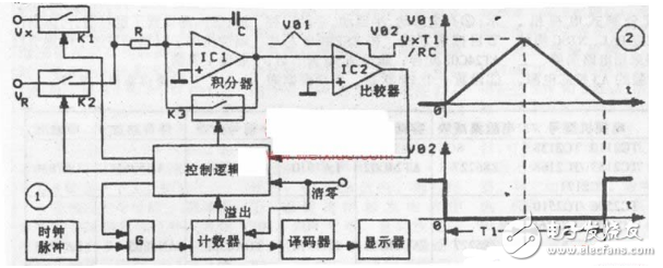


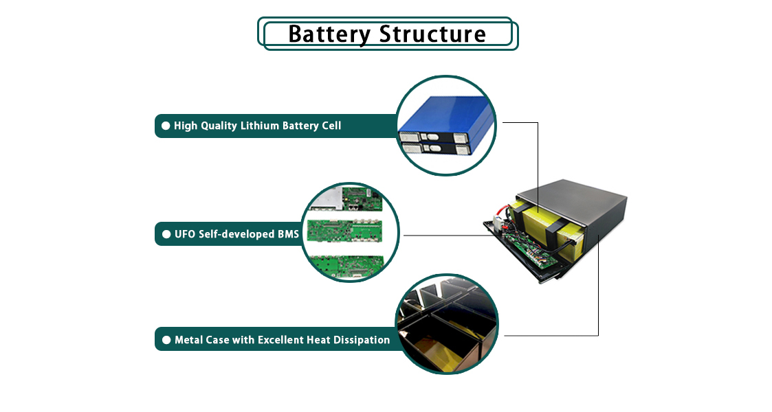
Feature of Rack Mount LiFePO4 Battery for Telecom Towers
Digital multimeter circuit diagram Daquan (analog-to-digital conversion circuit / display driver circuit)
Digital multimeter circuit diagram (1)