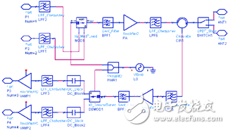
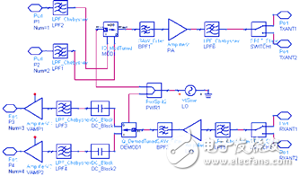
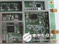
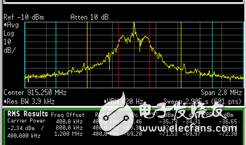
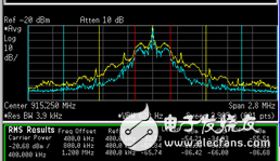
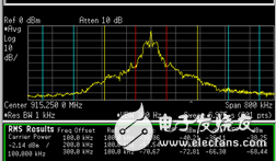
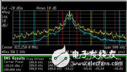
Radio Frequency Identification (RFID, Radio Frequency IdenTIficaTIon) is a multi-disciplinary new technology that combines radio, chip design and computer. In particular, the development of ultra-high frequency (UHF) standard ISO18000-6C and the development of its system have made RFID The application prospects are broader. Usually a UHF RFID system includes tags, readers, antennas and background controllers, etc. See Figure 1, where the reader is one of the most difficult and important components. The communication between the tag and the reader is to transmit the data of the tag to the reader by the backscattering principle, so that the reader needs to transmit the carrier signal to carry the data back to the tag=, such a working mode exists to receive the tag signal. At the same time, the transmit link is always transmitting carrier signals. If the transceiver link is poorly isolated, there will be a carrier signal leakage of the transmit link to the receiving link being too strong, resulting in saturation of the receive link, linear degradation and phase noise of the transmitted carrier signal affecting the demodulation of the received signal and failing to identify the tag data. The traditional reader/writer design adopts the separation of the transmitting and receiving antennas to increase the isolation of the transmitting and receiving signals and avoid excessive leakage of the transmitted carrier signal. However, the type of the reader is relatively large, high in cost, requires multiple antennas, and is troublesome to install. In this paper, the zero-IF scheme is used to simulate and analyze the RF module index design of the single-antenna reader and receiver. The problem of poor isolation between the single-antenna reader and receiver is better than that of the transceiver. The phase noise index of the transmitted carrier signal is determined. Receive link noise figure and P1dB compression point index, so as to design a high-integration two-band transceiver single-antenna reader RF module in UHF band (902MHz-928MHz), the output power can reach 1W, and the read tag distance can reach 5 Above the meter. Figure 1 Block diagram of the RFID system In this paper, the zero-IF scheme is used, as shown in Figure 2, the two sets of transceiver single-antenna RF module design block diagram. For comparative analysis, a block diagram of the two sets of transceiver two-antenna RF modules shown in Figure 3 is given. Figure 2 Block diagram of two sets of transceiver single antenna RF modules Figure 3 Block diagram of two sets of transceiver two-antenna RF modules This paper simulates the difficulty of transmitting and receiving a single antenna, that is, the strength of the transmit antenna echo signal (carrier) and the influence of its phase noise on the receiver receiving the tag response signal. According to the analysis result, the transmit carrier phase noise, the receiver input noise figure and the input are determined. P1dB compression point These three important RF module indicators. Set the reader to read the tag 5m away, the output signal power is 1W, the tag reflects 50% of the input signal [5], the normal tag requires 50uW (-13dBm) of receiving power for normal operation, according to the above conditions and free space The electromagnetic wave transmission model formula [5] can calculate the tag response signal power P(TR) received by the reader, and the tag receives the signal power P(RT) of the reader, assuming the tag dipole antenna gain is 1.64, the transmitting antenna The gain is 6dBi and the operating frequency is 915.25MHz. P (RT) = 30dBm + 6dB + 10log (1.64) + 20log (3/9.1525) - 20log (4 * 3.14 * 5) =-7.5dBm"-13dBm P(TR)=10log(P(RT)*0.5)-(30+7.5)dB =-48.0dBm Assuming an antenna return loss of -15 dB, the antenna is reflected back to the transmit carrier signal power P (CW) of the receive link, P (CW) = 30dBm-15dB=15.0dBm The device (switch, directional coupler, filter) loss before setting low noise is 5.5dB. In addition, the demodulation of general PR-ASK signal (250KHz, Tari=25us, X=0.5) requires 10dB signal-to-noise ratio. According to the above analysis and assumptions, the receiver link analysis model shown in Figure 2 is established in Agilent ADS2008. The antenna port input is -51.5dBm (considering that the edge signal is only 50% of P(TR), the sensitivity is less than the useful signal), the center frequency The 915.50MHz PR-ASK signal (250KHz, Tari=25us, X=0.5 tag response signal) has a superimposed power of 15.0dBm and a center frequency of 915.25MHz (including phase noise). The signal is established in accordance with ISO18000-6C. (FCC) Specification [1]. Through simulation analysis, it is determined that the input P1dB compression point of the receiver needs about 17.1dBm; the input noise figure can be very large, less than 40dB, that is, no effect; the phase noise of the transmitted carrier signal is less than -128.5dBc/Hz (offset 250KHz), the indicator The design is more difficult, but it is very important for the performance of the single antenna. It can improve the design of the indicator by improving the standing wave and gain of the antenna. In addition, because the noise figure is low, the input P1dB compression point is required to be high. Add attenuator before putting it down to reduce the requirement for low noise compression points. According to the above analysis, it can be seen that the single-antenna transmission and reception scheme has high requirements for the phase noise of the transmitted signal and the P1dB compression point of the receiving link because its isolation is only 15 dB. The isolation of the transceiver dual antenna scheme can generally reach 40dB, so the design of the phase noise of the transmitted signal and the P1dB compression point of the receiving link is relatively easy, but the cost is high and complicated. According to the above simulation analysis results, this paper uses the zero-IF scheme to design the RFID module RF transceiver module with UHF frequency band with high integration and single antenna transmission. The actual object is shown in Figure 4. Size: length & TImes; width & TImes; height = 53.5 Mm × 51.5 mm × 6 mm. Figure 4 Physical diagram of two RF antenna modules In this paper, the output signal power is actually measured in the case where the modulation mode is DSB-ASK (400KHz, Tari=6.25us, X=0.5) and PR-ASK (250KHz, Tari=25us, X=0.5). Signal spectrum and its template. In both cases, the output power reaches 1W, and the modulation mode of the DSB-ASK is shown in Figure 5 (including the carrier signal). The spectrum of the superimposed tag response signal is shown in Figure 6. The modulation mode is PR-ASK. The output spectrum of the transmitted signal is shown in Figure 7 (including the carrier signal), and the spectrum of the superimposed tag response signal is shown in Figure 8. From the test results, the DSB-ASK signal fully satisfies the spectrum template of the ISO18000-6C dense reader (the first adjacent channel and the main channel power ratio is less than -30dBc; the second adjacent channel and the main channel power ratio is less than -60dBc) The third adjacent channel and main channel power ratio is less than -65dBc). However, the PR-ASK signal is 5 dB in the second adjacent channel and is correlated with the input baseband signal difference. Figure 5 DSB-ASK transmit output signal spectrum (Frequency: 915.25MHz; 400KHz, Tari=6.25us, X=0.5) Figure 6 DSB-ASK transmit output signal superimposed tag response signal spectrum (yellow); transmit output signal spectrum (blue) (Frequency: 915.25MHz; 400KHz, Tari=6.25us, X=0.5) Figure 7 PR-ASK transmit output signal spectrum (Frequency: 915.25MHz; 250KHz, Tari=25us, X=0.5) In addition, this paper also carried out the reader read tag test, using 6dBi antenna, measuring the modulation mode of PR-ASK (250KHz, Tari=25us, X=0.5) readers read the tag's ability, which can be read Labels 5.5m away from the antenna. A single tag can read up to 32 bits per second from the reader at 3.8m. Figure 8 PR-ASK transmit output signal superimposed tag response signal spectrum (yellow; transmit output signal spectrum (blue) (Frequency: 915.25MHz; 250KHz, Tari=25us, X=0.5) In this paper, according to the requirements of ISO18000-6C standard, the zero-IF scheme is used to establish the simulation model to analyze the design of the RF module of UHF frequency (902MHz-928MHz) RFID reader under the condition of transmitting and receiving single antenna, and the carrier phase noise is given. The noise figure and the input P1dB compression point are the analysis results of the three important RF module indicators. Finally, the high-integration RF module is realized according to the analysis result. The length*width*height size is only 53.5mm*51.5mm*6mm. The test results show that the signal spectrum template performance index meets the requirements of the ISO18000-6C (FCC) intensive reader, and the distance and speed of the actual reading label reach a high level. The design of the RF module of the transceiver single antenna scheme greatly reduces the size and cost of the conventional transceiver for transmitting and receiving dual antennas. Mini PC
Are you tired on big and messy wires on traditional computer tower? If yes, mini pc bring clean and space saving working environment back to you. Whatever daily tasks, like browsing web pages, documents checking or making, online teaching or learning, entertainments, etc. Or heavy duty handling, like photshops, video or music editing, gaming, apps developing, engineering drawing, designing jobs, etc. You can always find a right pc mini intel at this store.
Mini PC Office is an most and popular series designed for those who mainly run WPS, photoshops, PR, email, entertainments, etc. Sometimes, also call it as mini pc officeworks or home assistant mini pc.
Mini Gaming PC comes with higher level processors, like intel i3, i5, i7 10th, 11th or 12th; bigger memory and storage, like 16GB or 32GB ram, 512gb up to 1tb. Of course, rich slots support linking with two or more monitors or devices.
Except mini pc windows 11, there are also All In One PC , Student Laptop, Gaming Laptop , Android Tablet, Yoga Laptop , etc.
Mini PC Windows 11,High Performance Mini PC,Mini PC DDR4,PC Mini Intel Henan Shuyi Electronics Co., Ltd. , https://www.shuyiminipc.com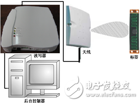
Highly integrated UHF band RFID reader RF module design analysis
1 Introduction