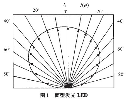
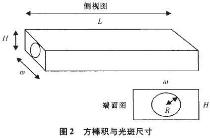
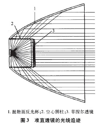
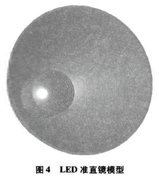
LED (1ight emitting diode) LED is a new solid light source with competitiveness in the 21st century. It has the advantages of high efficiency, pure light color, low energy consumption, long life, reliable and durable, no pollution, and flexible control. As LED technology continues to improve, the luminous flux and efficacy of LEDs will continue to increase. LED technology is bound to open up a new era of lighting technology revolution. Miniaturization and long life are the development direction of modern projection technology. In recent years, with the advent of high-brightness LED devices, new possibilities for the long life and miniaturization of modern projection display systems have been provided. LEDs have the advantage that traditional light sources cannot be replaced in the application of projection display systems. However, due to the difference in shape and illuminating characteristics of the LED and the shape and illuminating characteristics of the existing projection light source, the LED cannot be directly applied to the existing lighting system, and the requirements for miniaturization of the projection system cannot be met. Therefore, in the process of using LED as the projection light source, it is necessary to adopt a new light distribution method to re-distribute the LED with cosine distribution of light intensity, and finally realize a uniformly distributed rectangular spot. Today, the theory of non-imaging optics is quite complete, and many of its principles have penetrated into every field of life. There are also many literatures that introduce it to the projection system. This design uses a square rod homogenizing method. The unique collimation structure realizes the projection light path of uniform illumination. The optical device used is simple, compact, and uniform than the compound eye. The system has high energy utilization and better uniformity. Therefore, the development prospect of the square stick lighting system applied to the LED projector is very broad. 1 Design principle 1.1 Optical characteristics of LED The LED can be divided into a surface-emitting type and an edge-emitting type, and the surface-emitting type light-emitting surface is parallel to the PN structure plane, and the edge-emitting type emits light from one end surface (perpendicular to the junction plane) of the PN junction. The surface-emitting type LED has a larger optical power than the side-emitting type, but the light-emitting surface is large and the light-emitting angle is also large. When the light distribution is not performed once, the light-emitting effect is as shown in FIG. It can be seen from Fig. 1 that the surface-emitting type LED has a large illumination angle, and the light intensity is similar to the Lambertian distribution, that is, the light intensity distribution of the LED chip is a cosine distribution that is perpendicular to the axis direction of the LED illumination surface, and the cosine distribution is The light intensity in the line direction (ie, the zero angle) is Io, and the angle between any direction and the normal is 0, then the light intensity in any direction is satisfied. Since the light intensity of the LED satisfies the distribution of FIG. 1, in order to improve the utilization of light energy, the surface-emitting LED needs to be secondarily distributed. 1.2 Optimization of square rod integrator In a projection display system, the light emitted by the light source is uneven, and the emitted light is very divergent. After the collimation and turning, the shape is generally circular instead of the rectangular shape of the display (4:3 or The rectangle of 16:9). The role of the square bar is to shape and uniformly illuminate the light source. It is a superimposed non-imaging optics. The principle is similar to that of an optical fiber, and the incident beam is reflected multiple times in the square bar to make the outgoing spot uniform. The square rod can be either solid or hollow. If it is solid, then the light that occurs in the square rod is total reflection, which is more efficient than the hollow one. If it is hollow, it can achieve the same illumination uniformity in a shorter length. Because the light has a larger angle in the hollow square bar, when the length is the same, the light will be reflected more slowly in the hollow square bar than the solid one. From the energy point of view, the length of the square rod is directly proportional to the loss of energy, but the length of the square rod should not be too short, because the incident light needs to be reflected in the square rod a sufficient number of times to achieve uniformity of the spot. Regarding the relationship between the length of the square rod and the uniformity, the literature gives the following expression: Where Λ denotes uniformity, l is the length of the square rod, and φmax is the largest aperture angle in the rod mirror, From the point of view of Lagrange invariant, the size of the square bar is not as large as possible, but there is such a size. Under this condition, the energy utilization rate is the highest, and the formula for determining the initial size is given. A variant of (2). 2 projection lighting system design 2.1 Collimation structure The illumination angle of the LED can be divided into two parts: 0≤0≤45. (small angle area); 45 o ≤ 0 In Fig. 3, the part referred to by 1 is a parabolic reflector, which may be made of glass or high temperature resistant plastic, and the inner surface thereof needs to be coated with a reflective film with a higher reflectivity; It is a hollow cylinder, the material used is the glass with higher transmittance; the part referred to by 3 is a Fresnel lens, which can be mounted on the hollow cylinder, and the material used is PMMA. Figure 4 is a three-dimensional model of this collimation structure. Compared with the common rrIR type collimation structure, it has the advantages of short development cycle and low processing cost. However, compared with the collimated structure, its drawback is that the length is long, which is not conducive to the miniaturization of the projection system. 2.2 Coupling structure The design uses red, green and blue LED light sources. The wavelengths are standard three primary color wavelengths, which are 435.8 nm (blue), 546.1 nm (green), and 700 nm (red), respectively. Since the red light source and the blue and green light sources respectively have a light direction of 900, it is necessary to add an optical device to couple these mutually perpendicular rays into one direction. Here, a dichroic mirror is selected, the first function of which is to reflect blue light through red light, so that red and blue light are coupled in one direction; the second function is to reflect red light and blue light through green light. Eventually the three colors of light are coupled into one direction. The size of the second dichroic mirror is the same as the cross-sectional diameter of the beam. In order to collect more energy and converge as many beams as possible into the square rod integrator, it is necessary to add a focusing lens in the optical path to shrink the beam, and finally the light enters the square rod integrator to perform spot shaping and achieve a uniform light effect. 
 (1)
(1)  (2)
(2)  It is the diagonal length of the square bar section (Figure 2). The square rod is generally connected to the amplification system, and the subsequent amplification system can only work effectively within a certain numerical aperture range. Therefore, some people refer to the optical expansion amount or the Lagrangian invariant to analyze the most suitable size of the square rod integrator. . The literature analyzes the change of the optical expansion after the square rod is transmitted, and the system has the maximum light energy utilization rate when the optimal ratio of the height of the rod section to the radius of the incident spot is 1.535 (ie, H=1.535R).

