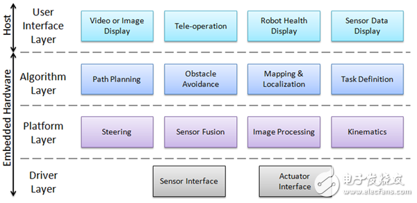
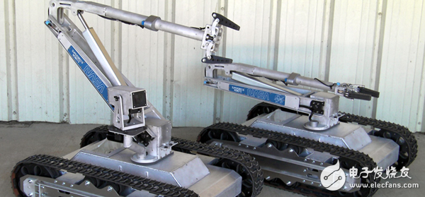
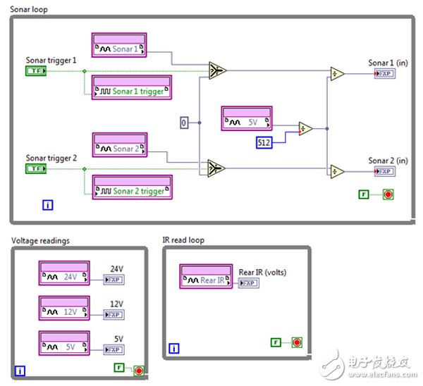
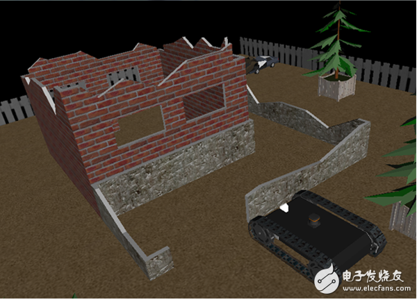
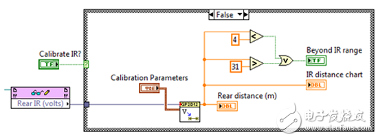
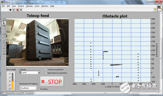
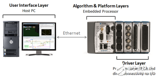
The robotic software architecture is a hierarchical set of typical control loops that includes advanced task planning, motion control loops, and ultimately field-programmable gate arrays (FPGAs) on high-end computing platforms. In the middle, there are loop control path planning, robot trajectories, obstacle avoidance and many other tasks. These control loops can run at different rates on different compute nodes, including desktops, real-time operating systems, and custom processors without an operating system. At some point, parts of the system must run together. Often, this requires pre-defined a very simple interface between the software and the platform—just as simple as controlling and monitoring direction and speed. It is a good idea to share sensor data at different levels of the software stack, but it will cause considerable trouble for integration. The philosophy of every engineer or scientist involved in robot design is different. For example, the same architecture works well for computer scientists and may not work properly with mechanical engineers. As shown in Figure 1, the proposed mobile robot software architecture consists of a three- to four-layer system represented by the following figures. Each layer in the software depends only on the specific system, hardware platform, or the ultimate goal of the robot, and is completely unrelated to the content of the upper and lower layers. Typical robot software includes drivers, platforms, and algorithm layer components, while applications with user interactions include a user interface layer (which may not require full autonomy). Figure 1. Robotic Reference Architecture The architecture in this example is an autonomous mobile robot with a robotic arm that performs tasks such as path planning, obstacle avoidance, and mapping. The range of applications for such robots is extensive in the real world, including agriculture, logistics or search and rescue. The onboard sensor includes an encoder, an inertial measurement unit (IMU), a camera, and multiple sonar and infrared (IR) sensors. Sensor fusion can be used to integrate localized encoder and IMU data and define a robot environment map. The camera is used to identify the object held by the carrier robot, and the position of the robot is controlled by the kinematic algorithm performed on the platform level, and the sonar and infrared sensors can avoid obstacles. Finally, the steering algorithm is used to control the movement of the robot, ie the movement of the wheel or track. Figure 2 is a NASA robot based on a mobile robot architecture. Figure 2. Mobile robot designed by SuperDroid Robots Developers can use NI LabVIEW system design software to implement the platform layer of these mobile robots. LabVIEW can be used to design complex robotic applications—from robotic arms to autonomous vehicle development. The software extracts I/O and integrates with multiple hardware platforms to help engineers and scientists improve their development efficiency. The NI CompactRIO hardware platform is very popular in robot development and includes integrated real-time processor and FPGA technology. The built-in features of the LabVIEW platform enable data communication between each layer, transferring data over the network and displaying it on a host PC. As the name implies, the driver layer handles the underlying driver functions required for robot manipulation. The components at this level depend on the sensors and actuators in the system, as well as the hardware on which the driver software is running. In general, the module at this level collects the setpoints of the exciters in the engineering units (position, speed, force, etc.) and generates the underlying signals to create the corresponding triggers, which may include code to turn off these setpoint cycles. Similarly, the module at this level captures raw sensor data, converts it into useful engineering units, and transmits sensor values ​​to other architectural layers. The driver layer code in Figure 3 was developed using the LabVIEW FPGA Module and executed on the embedded FPGA module of the CompactRIO platform. Sonar, infrared, and voltage sensors are connected to the digital I/O pins of the FPGA, and the signals are processed in a continuous loop structure that is truly parallel execution on the FPGA. The data output by these functions is sent to the platform layer for further processing. Figure 3. Driver layer interface for sensors and actuators The driver layer can be connected to the actual sensor or exciter, or to the I/O in the environment emulator. In addition to the driver layer, developers can switch between emulation and actual hardware without having to modify any layers in the system. Figure 4 shows the LabVIEW Robotics Module 2011, which includes a physics-based environment simulator, so users can switch between hardware and simulation, eliminating the need to modify any code except the hardware I/O module. Developers can use tools such as the LabVIEW Robotic Environment Simulator to quickly validate their algorithms in software. Figure 4. If simulation is required, the environment simulator must be used in the driver layer. The code in the platform layer corresponds to the physical hardware configuration of the robot. The underlying information in this layer and the complete high-level software can be bidirectionally switched, frequently switching between the driver layer and the higher layer algorithm layer. As shown in Figure 5, we used the LabVIEW FPGA read/write node to accept raw infrared sensor data from the FPGA and perform data processing on the CompactRIO real-time controller. We use the LabVIEW function to convert raw sensor data into useful data—in this case distance—and determine if we are outside the 4m to 31m range. Figure 5. The platform layer translates between the driver and algorithm layers The components in this layer represent the high-level control algorithms in the robot system. Figure 6 shows the robot needs to complete the task, you can see the module acquisition system information in the algorithm layer, such as position, speed or processed video image, and make control decisions based on all feedback information. The components in this layer are able to plan a map for the robot environment and plan the path based on obstacles around the robot. The code in Figure 6 shows an example of using a vector field histogram (VFH) to avoid obstacles. In this example, the distance data is sent from the platform layer to the distance sensor and received by the VFH module. The output data of the VFH module contains the path direction, which is sent directly to the platform layer. At the platform level, the path direction is input to the steering algorithm and the underlying code is generated and sent directly to the motor on the drive layer. Figure 6. The algorithm layer makes control decisions based on feedback information. Another example of an algorithmic layer component is a robot that searches for a red spherical object and picks it up using a robotic arm. The robot uses its set approach to explore the environment while avoiding obstacles – this requires a combination of search algorithms and obstacle avoidance algorithms. When searching, the platform layer module processes the image and returns information about whether the object was found. After the ball is detected, the algorithm generates a motion trajectory from which the arm ends can grab and pick up the sphere. Each task in the example has a high-level goal that is independent of the platform or physical hardware. If the robot has multiple high-level targets, then this layer also needs to include arbitration to sort the targets. The application in the user interface layer does not need to be completely independent, it provides physical interaction between the robot and the operator, or displays relevant information on the host PC. Figure 7 shows the graphical user interface with real-time image data on the onboard camera and the XY coordinate of the obstacles on the map. Servo angle control allows the user to rotate the onboard servo motor connected to the camera. In this layer you can also read input data from a mouse or joystick, or drive a simple text display. Components in this layer, such as GUIs, have very low priority; similar components such as emergency stop buttons need to be bundled with code in a deterministic manner. Figure 7. User interface layer allows users to interact with the robot or display information Depending on the target hardware, the software layer may be distributed across multiple different targets. In many cases, each layer runs on a computing platform. For an indeterminate application, the software target is a single PC running Windows or Linux. For systems that require tighter timing constraints, the software targets a single processing node with a real-time operating system. Given the small size, power requirements, and hardware architecture of CompactRIO and NI Single-Board RIO, they are the ideal computing platform for mobile applications. The driver, platform, and algorithm layers can be distributed across real-time processors and FPGAs, as shown in Figure 8, and the user interface layer can run on a host PC if needed. High-speed components such as motor drivers or sensor filters can operate deterministically on the FPGA fabric without taking up the processor's clock cycles. The middle layer control code on the platform and algorithm layers can be deterministically run on the real-time processor in a priority loop, while the built-in Ethernet hardware can transfer the information to the host PC to generate the user interface layer. Figure 8. Mobile Robot Reference Architecture mapped to CompactRIO or NI Single-Board RIO embedded systems A brief introduction to the mobile robot software architecture in the literature indicates that there are many different ways to create robot software for this topic. This article gives a broad answer on how to build mobile robot software; however, any design requires prior consideration and planning to adapt to the architecture. In return, a well-defined architecture helps developers easily work on projects in parallel, dividing the software into a clear interface hierarchy. In addition, dividing the code into modules with explicit input and output capabilities can help reuse code components in future projects. Vcsel Bare Chips,Surface-Emitting Laser Bare Chips,Laser Bare Chip Engraving,Laser Bare Chips AcePhotonics Co.,Ltd. , https://www.acephotonics.com