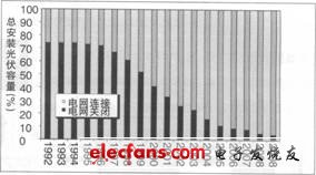
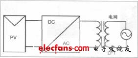
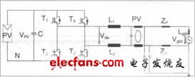
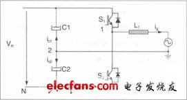
1. Non-isolated photovoltaic grid-connected inverter 1.1 Photovoltaic grid-connected power generation system The contribution of photovoltaic power generation to world energy is increasing year by year, which is obvious to all. IEA PVPS data show that in 2009, the project member countries installed a total of 6.2GW of photovoltaic capacity (about 7GW installed globally), of which more than 95% are grid-connected systems, as shown in Figure 1. Figure 1 The contribution of photovoltaic power generation to world energy increases year by year Source: IEA PVPS, InternaTIonal Energy Photovoltaic Power Systems Programme 1.2 Photovoltaic power generation system The photovoltaic power generation system is composed of photovoltaic cell arrays and grid-connected inverters (see Figure 2). The grid-connected inverter plays an important role in determining the performance and cost of the power generation system. According to whether there is a transformer, grid-connected inverters can be divided into isolated and non-isolated types, including: industrial frequency isolated grid-connected inverter, high-frequency isolated grid-connected inverter, non-isolated grid-connected inverter (single stage Type and multi-level type) etc. The power frequency isolated grid-connected inverter (as shown in Figure 3) has the advantages of electrical isolation and elimination of current DC components. However, it has a large volume and high price, with a system efficiency of only 94% -96%. The high-frequency isolated grid-connected inverter (Figure 4) has the advantages of electrical isolation, volume, weight, and cost reduction, but the system efficiency is only 90% -95%. Non-isolated grid-connected inverters are divided into single-stage non-isolated grid-connected inverters and two-stage non-isolated grid-connected inverters. Single-stage non-isolated grid-connected inverters are suitable for higher PV voltage and power; while two-stage non-isolated grid-connected inverters are suitable for PV arrays with a wide voltage range, they all have the highest efficiency of 98.8%, small size and weight Light and low cost, but its disadvantage is the electrical connection between the battery panel and the power grid. Figure 2 Composition of photovoltaic power generation system Figure 3 Structure diagram of power frequency isolated grid-connected inverter The electrical connection provides a circulation path for leakage current and is the biggest obstacle to the application of high-efficiency non-isolated photovoltaic grid-connected inverters. Leakage current problems will create a parasitic capacitance of 150nF / kWp, causing a switching frequency common mode voltage source. Most of the current strategies using circuit structure SPWM modulation. Figure 4 High-frequency isolated grid-connected inverter 2. Common circuit topology of non-isolated grid-connected inverter In the past, we often used full-bridge grid-connected inverters with bipolar SPWM modulation (Figure 5 shows its topology). Because of its low efficiency, it is often used in low-power applications and there are no patent barriers. Figure 5 Bipolar SPWM modulated full-bridge grid-connected inverter Here we will introduce several patented topologies. 2.1 Sunways' patent topology (Figure 6) Single-phase two-stage series: AT 2700/3000/3600/4500/5000: Single-phase single-stage series: NT 2500/3700/4200/5000; Three-phase two-stage series: Three-phase IxIT 10000/11000/12000. Figure 6 Sunways' patent topology 2.2 SMA's patent topology (Figure 7) Single-phase two-stage series: SB3000TL / 4000TL / 5000TL; Single-phase single-stage series: SMC6000TL / 7000TL / 8000TL / 9000TL / 10000TL / 11000Tlo Figure 7 SMA's patent topology 2.3 Half-bridge topology The two-level SPWM half-bridge has no patent barriers and is therefore widely used; in addition, there are unipolar SPWM three-level half-bridges. 3. Improved full-bridge non-isolated photovoltaic grid-connected inverter Let's first look at the model of single-phase grid-connected inverter leakage current analysis (see Figure 8) how to solve the problem of single-phase grid-connected inverter leakage current. Filtering branch: dominated by the network filter, EMI filter and grid parasitic parameters, it plays a leading role in the impedance of the common mode current loop; Parasitic branch: It is composed of parasitic capacitance at the midpoint of the bridge arm and affects the impedance of the common mode current loop: We have summarized two ways to eliminate leakage current through the leakage current analysis model of single-phase grid-connected inverter (Figure 9): (1) Under the premise that the circuit and parasitic parameters are symmetrical (that is, meet Figure 8 Model of leakage current analysis of single-phase grid-connected inverter Figure 9 Model of leakage current analysis of single-phase grid-connected inverter VCM-DM: 0), the VCM voltage generated by the SPWM switching method is a constant value; (2) When the VCM voltage generated by the SPWM switching method is high-frequency time-varying, the circuit parameter matching makes VCM + VCM-DM = consto. Leakage current suppression technologies for full-bridge single-phase grid-connected inverters include: (1) Under the premise that the circuit and parasitic parameters are symmetrical (that is, VCM-DM: O is satisfied), the v voltage generated by the SPWM switching method is a constant value. Common circuits are as follows: Full bridge circuit with AC bypass link; Full bridge circuit with DC bypass link; Full bridge circuit with DC side bypass clamp; Improved full-bridge circuit optimized based on function and efficiency. Add a controllable switch tube and voltage divider capacitor to form a bidirectional clamping branch. Ningbo Autrends International Trade Co.,Ltd. , https://www.supervapebar.com


