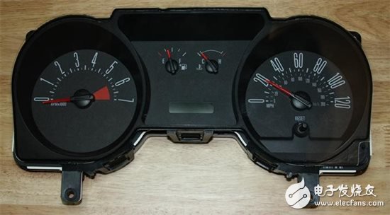
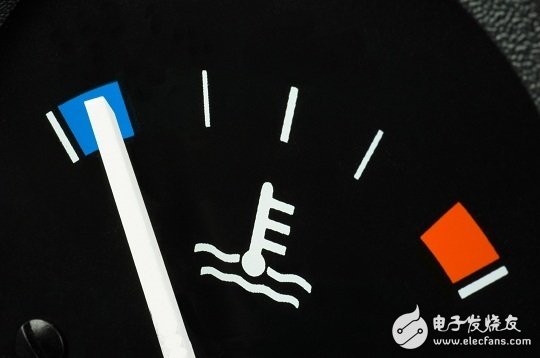
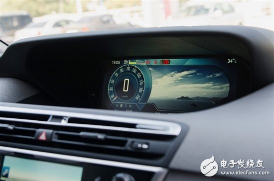
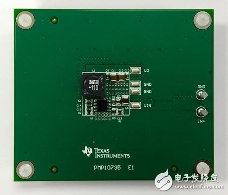
I wonder if you still remember, the dashboard was very boring? They usually have five functions: speedometer, tachometer, odometer, fuel gauge and thermometer. Figure 1: In the past, the dashboard was simple and the power consumption was much lower than it is now. In the unlikely event that you can't stand the spouse's embarrassment and finally agree to drive to Winnipeg, the more stylish dashboard can display speed values ​​in miles per hour and kilometers per hour. All dials are mechanical. The only way to use a graphical display is the amount of oil that looks like a key sticking out of the water. Figure 2: The graphical display in the previous dashboard was very limited, including the master key that protruded from the water. In the past few years, dashboards have become more and more interesting. If you haven't upgraded your 81 Scirocco yet, they are much better than before. Figure 3: Currently, the dashboard is already digital and consumes more power. Most current dashboards are digital, using LCDs and LEDs as backlight sources (Figure 3). In fact, if you only have a 3.5-inch display, it is relatively low-end. The current trend is a 7-inch display, and if you can afford a high-end vehicle, the 12-inch display is also standard. Of course, in addition to this, you can easily control the display by manipulating the buttons on the steering wheel. You can view all the information related to the vehicle on the dashboard, such as the song you are listening to (including the album cover), vehicle diagnostic information, and 3D display of the surrounding environment. All of these enhancements require more processing power. For low-end and mid-range dashboards, the best power balance for a converter that does not use a battery is in the 15W range (5VOUT x 3A). High-end dashboards with large screens can exceed 25W. In addition to basic specifications such as input voltage and output current, the next most important specification in the data sheet is likely to be quiescent current (IQ). In fact, it involves two numbers. Shutdown quiescent current is the current value when the regulator IC is completely disabled by an enable or shutdown pin. On the other hand, the standby quiescent current is the current when the device is enabled, but without load. With the ever-increasing electrification level in automobiles, more and more electronic components are connected to 12V batteries. Some of these electronic components will never be disabled. You can think about your key card. At the other end of this signal is a system circuit called the Passive Entry Start System (PEPS). The PEPS system must always be in the "on" state, waiting for the signal from the key fob. (Otherwise, you may have to use the key on the keychain, which we don't want to see.) In any case, since the PEPS system is always on, it always draws standby quiescent current from the battery. In the dashboard, several circuits are always on, as is the case in the PEPS system. For example, real-time clocks, CAN/LIN transceivers, and microcontrollers. For the entire dashboard, the typical overall current consumption allowed in standby is approximately 100μA, which is not easy to achieve with a processor that consumes 50μA easily. There are several different ways and means to solve this problem, as much as possible to reduce the power supply quiescent current in the instrument panel. Since the number of low quiescent current switching regulators has not been large until now, most common methods use a low quiescent current LDO in parallel with the switch. The switch will be disabled and the LDO can be used to wake up the downstream circuitry while drawing less current from the battery. At present, there are devices such as the LM43603-Q1, which have a standby quiescent current of 27μA, so you can not use the LDO. This greatly reduces the BOM cost. In addition, it is important to keep in mind that this value of 27μA is for synchronous devices—the asynchronous device data sheet will provide standby quiescent current only for the IC, excluding diodes. The current leakage in the diode can be as high as 1 mA at high temperatures, which can greatly exceed your expectations. In these cases, you need to eliminate any possible milliampere current consumption to match the quiescent current budgets that are particularly thought-provoking, and the new LM53603-Q1 can even better meet this requirement. You can also take a look at the data sheet, which has a value of 23μA. You may feel that the difference is not very big. However, the output voltage of the LM53603-Q1 is fixed, so no feedback resistor is required. Current leakage in the feedback resistor can easily increase the current consumption by 3-5μA in your system. In addition to eliminating hidden quiescent current sources in the system, the power of these synchronous devices is also within the 15W optimal power balance point mentioned above. As an engineer, if you really want to achieve outstanding performance with fewer external components, check out one of the two-layer reference designs unique to the LM53603-Q1 and LM43603-Q1 (Figure 4) shown below. Figure 4 : PMP10735 is a wide Vin, 3A step-down 2-layer reference design for automotive dashboards (with CISPR 25 Class 5 compatible TI Design) Other resources Consider using TI's SIMPLE SWITCHER® LM43603-Q1 and LM53603-Q1 voltage converters in your next design. Watch the video to learn how to use front-end protection circuitry to reduce quiescent current drain. Download these tested reference designs: Wide Vin, 3A Step-Down 2-Layer Reference Design for Automotive Dashboards (CISPR 25 Category 5 Compatible TI Design) Optimized 2-layer 15W power supply for EMI performance in automotive applications Start a power supply design with TI's WEBENCH® automotive design tool.
A Bridge rectifier is an Alternating Current (AC) to Direct Current (DC) converter that rectifies mains AC input to DC output. Bridge Rectifiers are widely used in power supplies that provide necessary DC voltage for the electronic components or devices. They can be constructed with four or more diodes or any other controlled solid-state switches.
Bridge rectifiers,Ultra Fast Switching Diodes,Fast Recovery Diode,Fast Switching Diodes,Diode Bridge Rectifiers Changzhou Changyuan Electronic Co., Ltd. , https://www.cydiode.com


