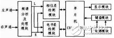
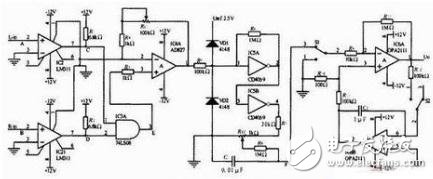
This paper mainly proposes a design method of stereo signal phase difference level difference tester. The single chip is used as the control core, which mainly consists of a phase difference detection module, a level difference detection module, a spectrum analysis and processing module, a power module, a keyboard and a display module. The LR stereo signal is processed by the spectrum analysis, shaping and duty cycle detection circuit, and the phase difference test is performed by measuring the duty ratio of the rectangular wave by using the zero-cross phase discrimination method. The LR signal is realized by the AD736 dedicated chip for AC/DC conversion, and the LR level difference is obtained by the single chip programming. In the case of stereo broadcasting or playback, if there is a phase difference and level difference between the left and right channel signals, the quality of the broadcasting or playback quality will be affected, and the phenomenon of sound image drift, volume reduction, noise increase and distortion may occur. The greater the difference in phase difference between the left and right channels, the worse the sound quality, and in the case of serious sound failure. In this paper, the stereo signal phase difference level difference tester is designed. Only when the phase difference level difference is accurately measured, and then the compensation circuit is used for correction, the quality of the broadcast or playback can be ensured, and the sound quality is better satisfied. The need for radio or music. As shown in Figure 1, it is a schematic block diagram of the stereo signal phase difference level difference tester. A design method of stereo signal phase difference level difference tester is proposed. The C8051F020 single-chip microcomputer is used as the control core, which is mainly composed of a phase difference detection module, a level difference detection module, a spectrum analysis and processing module, a power module, a keyboard and a display module. The LR stereo signal is processed by the spectrum analysis, shaping and duty cycle detection circuit, and the phase difference test is performed by measuring the duty ratio of the rectangular wave by using the zero-cross phase discrimination method. The LR signal is respectively AC/DC converted by the AD736 dedicated chip, and the LR level difference is obtained by the single chip programming. The whole system is controlled by a single-chip microcomputer, keyboard operation, and the LCD displays the phase difference level difference and related information. Figure 1 Block diagram of the stereo signal phase difference level difference tester 2.1 phase difference detection module 2.1.1 Block Diagram and Circuit Schematic As shown in Figure 2, it is a schematic block diagram of the phase difference detection module. As shown in Figure 3, it is the circuit principle of the phase difference detection module. The phase difference detection module is composed of a voltage comparator, an AND gate, an amplifier, a duty ratio detection circuit, and an instrument amplifier. As shown in Figure 3, IC2 LM311 and IC21LM311 and their surrounding devices form two voltage comparators. The L (A point signal) R (B point signal) left and right channel signals are respectively shaped by IC2 and IC21 voltage comparators. The wave signal (C point signal and D point signal) is then combined to obtain a rectangular wave (E point signal), and 74LS08 is an AND gate. The IC4 AD827 and its surrounding components form a non-inverting amplifier that amplifies the signal output from the AND gate. The IC5 CD4069 and its surrounding components form a duty cycle detection circuit that measures the duty cycle of two rectangular wave signals using a zero-crossing phase-detection method. A rectangular wave with a duty cycle of D is added to the input terminal, and a DC signal is outputted at the output terminal F. The value varies between 0 and 100 mV. This DC signal represents the duty ratio D and is an amount reflecting the phase difference. IC6 OPA2111 and its surrounding devices form an instrument amplifier for amplifying the output signal of point F. Since this signal value is 0~100 mV, it is a small signal, so the automatic zero-type instrument amplifier is used to ensure the tester has high precision. . When the switches S1 and S2 are simultaneously at "1", the automatic zero-zero function is completed; when the switches S1 and S2 are simultaneously at "3", it is a normal amplification function. The amplified signal is then applied to the A/D terminal of the microcontroller. The C8051F 020 has a 12-bit A/D converter inside. Figure 3 Phase difference detection module circuit schematic
Lost Mary OS5000 Vapes combine performance and style with their ergonomic shell and mesh coil for improved flavor profiles. Each Lost Mary Disposable Vape is rechargeable via USB-C charging cable and contains 13ml of vape juice. Lost Mary OS5000 rechargeable vapes, designed by Elf Bar, also provide a battery indicator that allows vapers to check on power levels while they are vaping. Green (high battery), blue (medium battery), and red (low battery) LED colors display the amount of charge left in the 650mAh battery.
Lost Mary vapes are a range of disposables that are easy to use and available in a wide range of flavours. With a focus on fruit and menthol blends, the Lost Mary BM600 vapes deliver a sweet and cool taste with every inhale – the same goes for the Lost Mary AM600 vapes. Speaking of inhaling, that`s all you need to get started, just inhale on your device`s mouthpiece and it will activate instantly. Plus, the 20mg nic salt in each delivers a smooth throat hit.
lost mary vape,lost mary bm3500,lost mary vape review,lost mary os5000,lost mary elf bar. Nanning Ousibang Information Technology Co., Ltd. , https://www.ousibangvape.com
