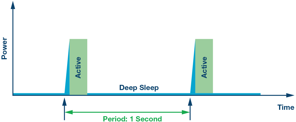
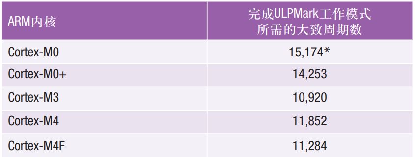
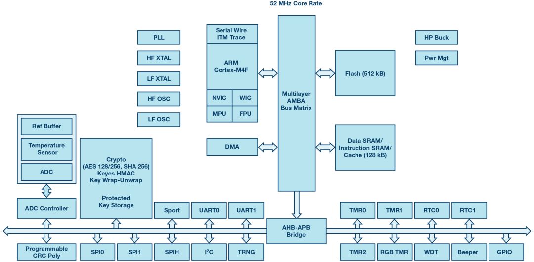
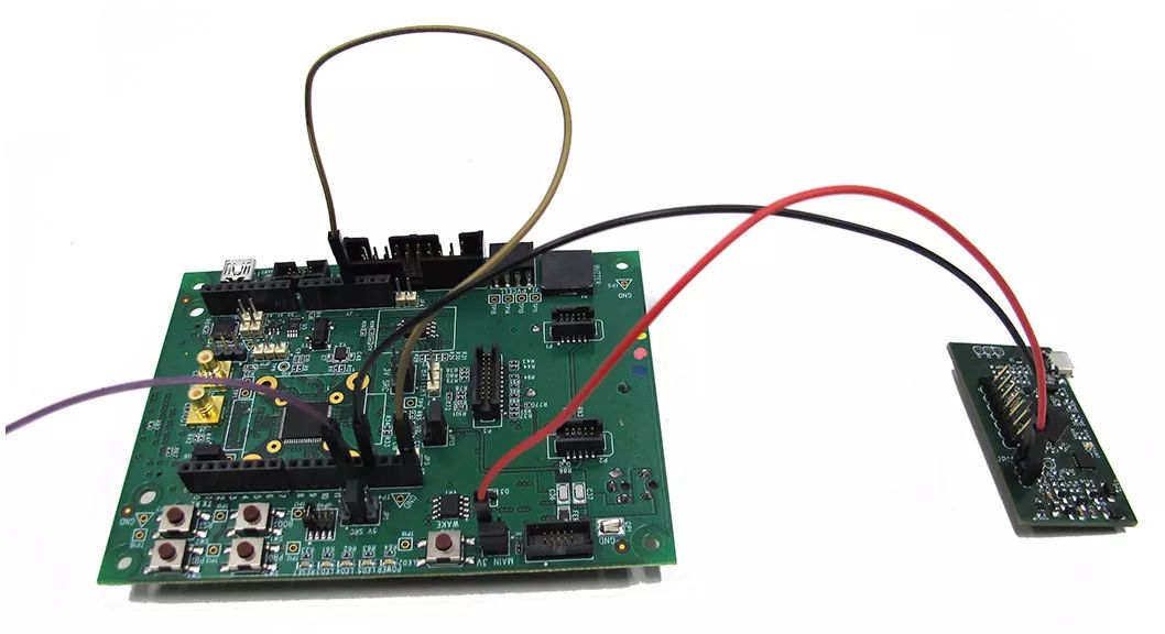
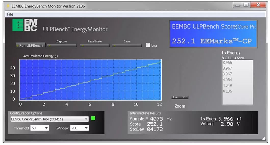
Driven by the Internet of Things, the industry has created huge demand for various battery-powered devices. This in turn has led to an increase in energy efficiency requirements for microcontrollers and other system-level devices. Therefore, Ultra Low Power (ULP) has become an overused marketing term, especially when used to describe microcontrollers. As a first step in understanding the true meaning behind ULP, you should consider its various implications. In this article, we will look at two Analog Devices microcontrollers to help you understand how to interpret the true meaning of ultra-low power consumption in this context. We will also discuss the EEMBC Alliance's certification mechanism as it ensures the accuracy of the scores and helps system developers choose the most appropriate microcontroller for their solution. As a starting point for understanding ULP, we first explain how to measure it. Developers often look at data sheets where they can find current values ​​per MHz and current values ​​in different sleep modes. The first problem is that when viewing the power consumption of a work, the data sheet usually does not explain the conditions under which the value is obtained. For example, code, voltage, and wait states on flash. Some vendors use work mode references, such as EEMBC CoreMark, while others use the same simple operations as the "while 1" statement. If there is a wait state on the flash, the performance of the microcontroller unit is reduced, increasing the execution time, thereby increasing the power consumption of the task. Some vendors offer values ​​for typical voltages, some provide values ​​for the lowest voltages, and some suppliers do not specify any voltage. Perhaps these differences are subtle, but without a standard, the comparison can only be a rough comparison. In general, deep sleep mode is explained in considerable detail in the data sheet, but again, the conditions for obtaining current consumption in these modes vary from vendor to vendor (eg, amount of memory or voltage reserved). In addition, in practical applications, users must also consider the power consumed to enter and exit these modes. This can be a trivial value, or it can be significant, depending on whether the device is in sleep mode or wakes up most of the time. The second question is how long does the device sleep? The balance between working mode and sleep mode is very important for determining ULP measurements. To simplify the process, EEMBC uses 1 second for its ULPMark-CoreProfile (ULPMark-CP); this is a benchmark test that many microcontroller vendors use as standards for data sheets. Note: The decision to use 1 second is considered a consensus of the EEMBC working group. Taking into account the working hours of the ULPMark-CoreProfile workload, the duty cycle will be around 98%. In this benchmark, the device wakes up once per second, performs a small amount of work (duty cycle), and then goes back to sleep. Typically, in the operating mode, the analog circuitry causes an offset in current consumption; therefore, minimizing the operating current and effectively using the deep sleep mode makes sense for optimizing the power usage of the entire system. Note that lowering the frequency will reduce the operating current, but the time will increase, and the offset caused by the analog circuit mentioned above will remain the same when the microcontroller is in operation. But what are the pros and cons of different choices for microcontrollers? What is the effect of the applied duty cycle and deep sleep current on the power consumed? The energy per cycle is a function of the duty cycle D (given as a percentage of the total time in sleep mode time) and can be defined by a simplified formula, assuming that the power to switch on and off is small. Among them, the slope is defined by ION, because ISLEEP is much smaller than ION, and the y-intercept is ISLEEP. This formula can help understand the duty cycle, where the operating current is more important than the sleep current. Figure 1. The duty cycle of the ULPMark-CP is 1 second. During this time, the device wakes up from deep sleep mode, performs a fixed workload, and then returns to deep sleep mode. Compare the ultra-low power (power) characteristics of two Analog Devices microcontrollers, the ADuCM4050 and ADuCM302x. In the ULPMark session, the ADuCM4050 and ADuCM302x scored 203 and 245.5, respectively. Keep in mind that this benchmark only operates on the core of the microcontroller unit (hence the name CoreProfile). How to explain the 18% difference? The ADuCM4050 includes an ARM® Cortex®-M4F with ARMv7E-M architecture. The ADuCM302x includes an ARM Cortex-M3 with ARMv7-M architecture. Although both cores have a three-stage pipeline with branch speculation, and the instruction set architecture of the two cores is similar, only the Cortex-M4F supports DSP and floating-point instructions. The ULPMark-CoreProfile does not have DSP instructions, so the Cortex-M4F device does not take advantage of the FPU. For benchmark analysis, the ADuCM4050 and ADuCM302x operate at 52 MHz and 26 MHz, respectively. The ADuCM4050 requires approximately 11,284 cycles to execute the ULPMark workload, and the ADuCM302x requires 10,920 cycles, which means that the former completes the active mode portion within 217 μs of the 1 second cycle, while the latter has a working time of 420 μs. The ADuCM4050 uses more cycles than the ADuCM3029 because of the different frequencies used (52 MHz and 26 MHz, respectively). The ADuCM4050's flash memory requires a wait state, while the ADuCM3029's flash memory has no wait state. The ADuCM4050 has a cache, so adding wait states on the flash does not have much impact because many instructions are executed from the cache and can be accessed at full speed (52 MHz) without additional wait states. Regarding execution time, as expected, the ADuCM4050 performs workloads faster than the ADuCM3029 because it runs twice as often as the ADuM3029. Table 1. The approximate number of cycles required to complete a ULP-Mark-CoreProfile workload on a popular ARM core. The number of cycles is an approximation because the number of cycles is also related to the compiler. *This is based on estimates of Cortex-M0+ and Cortex-M3 numbers. But why does the ADuCM4050 consume 10 μA/MHz more than the ADuCM3029? The reason behind this increase is that the former can operate at twice the frequency of the latter, thus requiring additional buffers to achieve timing constraints for higher frequencies. Compared to the ADuCM3029, the ADuCM4050 has some additional features: The memory size is doubled (both in SRAM and flash): 128 kB and 512 kB, while the ADuCM3029 is only 64 kB and 256 kB. Depending on your application needs, you may need additional storage. The frequency doubles: 52 MHz, while the ADuCM3029 has only 26 MHz, so the ADuCM4050 performs better. Added RGB timer. New security features have been added: protected key storage with key wrapping - unpacking and keyed HMAC with key unpacking. Three additional SensorStrobe outputs have been added. All SRAM content retention features have been added: the ADuCM4050 can hold up to 124kB, while the ADuCM3029 can only hold up to 32kB. Figure 2. The top 10 results of the ULPMark-CP, located on the EEMBC website (August 18, 2017). Depending on your application needs (power optimization, additional storage, performance, content retention, etc.), you can decide whether to use the ADuCM4050 or ADuCM302x products. With regard to deep sleep mode, the ADuCM4050 achieves lower sleep power consumption when running ULPMark-CoreProfile and retaining twice as much memory content as the ADuCM3029 (the former is 16 kB, while the latter is 8 kB). The reason for this improvement is that the newer ADuCM4050 products feature an enhanced architecture. ULPMark includes two operational states: active state and low power state (device is in sleep mode). These states are all included in the duty cycle of exactly 1 second. In the active state, each device performs the same workload. But as we have seen, productivity is affected by the architecture. In addition, it is also affected by the compiler. The compiler may choose to change and optimize the statement, causing the instruction combination to change. Depending on the needs of your application, you can optimize for size and speed to balance factors such as size and speed. Loop unrolling is a simple example where the number of branches executed and the ratio of code inside the loop will change. The compiler can still play an important role in finding a better way to calculate results, but the work done is equivalent. For example, the ULPMark-CP results for the ADuCM3029 may vary depending on the degree of optimization: 245.5 for speed height optimization, 232 for medium optimization, and 209 for low optimization. The ULPMark results of the Texas Instruments MSP430FR5969 are another example of the importance of the compiler. By applying a newer version of the IAR Embedded Workbench compiler, the results have increased by 5% - although I don't know what changes have been made to the internal compiler to implement this improvement (). Similarly, without a deeper understanding of proprietary compiler technology, it is impossible to know why the STMicroelectronics STM32L476RG has improved by 16% from the use of the ARMCC compiler to the IAR compiler. Both results of the Analog Devices MCU are generated using code compiled by the IAR compiler, but the versions are different. ADuCM4050 and ADuCM302x use IAR EWARM7.60.1.11216 and 7.50.2.10505, respectively. I also don't know what internal changes have been made. The two scores submitted use the no_size_constraints option corresponding to the optimization speed. ULPMark-CoreProfile uses a formula that takes the reciprocal of the energy value (10 cycles, the median of 5 average energy values ​​per second). Power is the sum of the power consumed by the device when it is in the workload (in the operating mode) and the amount of energy consumed when the device is in the sleep state. According to the ADuCM3029 data sheet, the operating current is typically 980 μA when running a prime code. This code is loaded into the cache to take advantage of its lower power consumption. For the ULPMark-CoreProfile code, since it is primarily linear code, there is not much benefit in enabling the cache, so the current consumption is similar to the current consumption (1.28 mA) shown in the data sheet for the disabled cache. Regarding the sleep current, ULPMark-CoreProfile requires LFXTAL and RTC to be enabled, so the current consumption in sleep mode is 830 nA (according to the data sheet). As mentioned above, the working time lasts for 420 μs. According to the data sheet number and execution time, the operating current is 1.61 μJ and the power consumed during sleep is 2.49 μJ. The scores based on these values ​​are consistent with the scores measured by the EEMBCEnergyMonitor software. One of the shortcomings of the first generation of ULPMark is that the operating rules limit the operating voltage to 3 V (the purpose of the workgroup is to establish a common level for all devices). Most modern MCUs operate much better at lower voltages (although this may be affected by temperature and operating frequency). For example, using a DC-DC converter to reduce the voltage from 3 V to 1.8 V, the STMicroelectronics STM32L476RG's ULPMark results have increased by 19%. Figure 3. Block diagram of the ADuCM4050. It integrates a 1.2 V low dropout regulator (LDO) and an optional capacitive buck regulator. The results announced are not the only ones used by DC-DC converters. STMicroelectronicsSTM32L476RG is not the only such device, but some devices integrate converters into the device itself, such as the ADuCM302x and ADuCM4050, which do not require external ICs to improve the power performance of the device. Still, using a DC-DC converter helps create a level playing field because it allows the device to operate at peak efficiency. For example, a device operating only at 3 V will not benefit from a DC-DC converter because it is already at an optimal (or possibly sub-optimal) level of efficiency. On the other hand, a device that can operate at 1.8 V but does not utilize a DC-DC converter will waste 64% of its power. In addition, for system designers prioritizing energy efficiency, if the system uses a 3 V battery, the additional cost of the external DC-DC converter may not be important. Care must be taken to use a DC-DC converter to avoid measuring the energy efficiency of the converter rather than the MCU. However, it must be considered that in practical applications, the DC-DC operating mode may have some disadvantages, such as the extended switching time between the working mode and the sleep mode. When using a DC-DC converter, you also need to consider the type of converter. Some converters are based on inductors and can cause problems such as larger area, higher cost, and electromagnetic interference (EMI). The ADuCM4050 and ADuCM302x devices use capacitor-based converters to avoid these problems. When analyzing ULPMark-CP results or data sheet values, it is important to recognize the existence of device differences. In other words, leakage current is an important factor when measuring the energy efficiency of a device, especially in sleep mode. Although traditional performance benchmarks are generally unaffected, factors such as temperature and humidity have a certain effect on the leakage current of the device, which in turn affects the results of ULPMark-CP. In terms of manufacturing, devices produced by the same supplier on different dates or from different wafers will be different. Even the power consumption of the same device may change (from 5% to 15% depending on the time and location of the measurement). Fundamentally, this means that the given ULPMark-CP score should be used as an energy efficiency guide. For example, a device has a ULPMark result of 245, while a device from a different wafer may score between 233 and 257 (assuming a 5% change). To ensure the authenticity of the score, vendors willing to certify their devices to send boards and tools to the EEMBC Technology Center (ETC) along with platform-specific profiles. EEMBC integrates platform profiles into its system files (including workloads) and measures scores multiple times on different boards. The certified score is the average of all measurements. In this way, EEMBC ensures that all scores are met under the same conditions (same workload, same power monitoring board, similar temperature, etc.). Figure 4 shows the connection settings for measuring the ULPMark-CP on the ADuCM3029 EZ-Kit. Figure 4. Board settings for measuring scores. In order to measure the score, EEMBC provides the EnergyMonitor software. After clicking the Run ULPBench button, the EnergyMonitor hardware powers the ADuCM3029 EZ-Kit board and measures the energy consumption of the configuration file. At the end of the execution, the software calculates the score and displays it on the screen. The software also displays the average energy consumption of the previous cycle in the history window. Figure 5. EnergyMonitor software - GUI. The ultimate goal of EEMBC is to provide multiple benchmark suites that enable users to fully evaluate the MCU. In addition to the ULP-Mark-CP, which focuses on the core efficiency of the MCU, the newly released ULPMark-PeripheralProfile (ULPMark-PP) focuses on operating various MCU peripherals such as ADC, PWM, SPI and RTC. In ULPMark-PP, operating power consumption and light sleep power consumption are important because the device performs multiple peripheral transactions in the workload. The results of ULPMark-PP are available on the EEMBC website; the ULP-Mark-CP and ULPMark-PP combinations are available or licensed for use by EEMBC members. Next I developed the IoTMark-BLE and SecureMark suites. The former focuses on measuring the efficiency of MCUs and radios transmitting and receiving data via Bluetooth®; the latter is a sophisticated security suite that measures the power and performance overhead of IoT devices implementing various encryption mechanisms. Both will be available to members and licensees by the end of 2017. Jiangmen Hongli Energy Co.ltd , https://www.honglienergy.com
