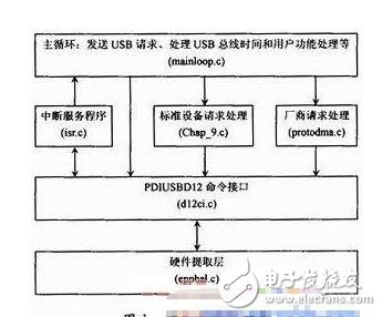
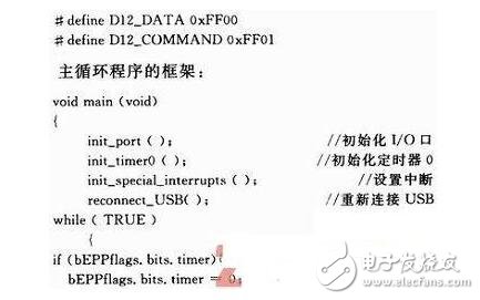
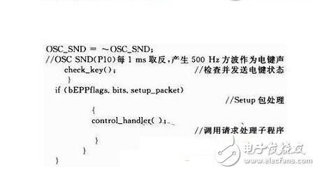
With the upgrading of computer technology, the USB interface has become the most important external device expansion interface on personal computers, and it is necessary to write its firmware program during the development of USB peripherals. The USB interface firmware program was developed here and developed in C language in the Keil C51 software environment. The main functions of the firmware program are introduced, the flow, structure and endpoint configuration of the firmware program are given, and the specific procedures of the key places are given. The firmware is simple and easy to modify and test, which increases the readability of the code and increases the versatility and portability of the program. When designing and developing a USB peripheral, developers mainly need to write three parts of the program: firmware, USB drivers and client applications. When the device is connected to the host (USB cable is plugged into the jack), the host computer can discover the new device and then establish a connection. Therefore, one of the primary purposes of writing firmware is to allow Windows to detect and identify devices. The firmware program can be developed in C language in the Keil C51 software environment. Keil C51 is a 51 series compatible single-chip C language software development system produced by Keil SOFtware Company of the United States. KeilC51 software provides a large number of library functions and powerful integrated development and debugging tools. It uses a full Windows interface and is convenient and practical. In addition, the object code generated by Keil C51 is very efficient, and the assembly code generated by most statements is very compact and easy to understand. Therefore, this article considers the use of this method to develop the USB firmware program of the PDIUSBD12 chip. The goal of the firmware design is to complete the command and data transfer and conversion between the host and the device, so that the PDIUSBD12 achieves the maximum transfer rate on the USB. Its operation is closely related to hardware, including USB device connection, USB protocol, interrupt processing and so on. In the system, when the PDIUSBD12 receives a packet from the USB, it generates an interrupt request to the CPU, and the CPU immediately responds to the interrupt. In the ISR (Interrupt Service Routine), the firmware reads the data and saves the data value to the cyclic data buffer, and then sets the flag of the corresponding event. The CPU continues the foreground program, detects the event flag, and executes the corresponding event task. The USB microcontroller firmware program usually consists of three parts: the initialization microcontroller and all peripheral circuits (including PDIUSBD12); the main loop part: this part is interruptible; the interrupt service routine can interrupt execution. According to the USB protocol, any transmission is started by the host, so that the microcontroller works as its foreground and waits for an interrupt. The host first sends a token packet to the USB device (here, PDIUSBD12). After receiving the token packet, the PDIUSBD12 sends an interrupt to the microcontroller. The microcontroller enters the interrupt service routine, first reads the interrupt register of the PDIUSBD12, and determines the type of the USB token packet. Then the corresponding operation is performed. Therefore, the USB single-chip program is mainly the writing of the interrupt service program, and the response to various token packets is completed in the USB single-chip program. The communication between the MCU and the PDIUSBD12 is mainly realized by the MCU issuing commands and data to the PDIUSBD12. The command words of PDIUSBD12 are divided into three types: initialization command word, data stream command word and general command word. PDIUSBD12 gives the code and address of various commands. The MCU first sends commands to the command address of PDIUSBD12, and then sends or reads different data according to the requirements of different commands. Therefore, each command can be made into a function, each function can be implemented by a function, and the function can be directly called later. The USB device startup process is as follows: (1) The USB device is connected to the USB port and issues a connection USB command; (2) The host issues a read device descriptor 2 times; (3) The host starts the corresponding device driver according to the device descriptor (vendor ID, product ID); (4) The device driver initializes the USB device: 1 read the device descriptor; 2 read the configuration descriptor; 3 Select the interface, endpoint (pipe), and determine the transmission method. When writing the USB MCU firmware program, the interrupt of the MCU should be set to level trigger. After the interrupt, the last transfer status register (command 40H~45H) must be read to clear the interrupt flag in the interrupt register, thus the interrupt output of PDIUSBD12. Change back to high level. The PDIUSBD12 firmware is written in a layered structure that is simple and easy to modify and test, which increases the readability of the code and increases the versatility of the program. The development of PDIUSBD12 firmware is generally based on the firmware source code provided by Zhou Ligong MCU. Since the firmware adopts a hierarchical sub-module structure, it is convenient to run a specific platform as long as the partial code is modified during the migration. The firmware program takes the building block structure as shown in Figure 1. 2.1 hardware extraction layer Epphal. The c file is the lowest level of code in the firmware. Since the hardware platform provided in the specific application is different, the file must be modified to suit the current application. The file mainly includes the function of reading and writing the PDIUSBD12 register, the connection between the control lines of the PDIUSBD12 chip and the I/O port of the MCU. There are two main ways to read and write PDIUSBD12: multiplexed address/data bus mode and A0 address bit mode. The circuit connections are completely different in different ways, so the read and write functions are completely different. This place uses the multiplexed address/data bus method, that is, the lowest bit of the address/data bus identifies whether the data is a data or a command on the bus, 1 represents a command, and 0 represents data. 2.2 D12 Command Interface D12ci. A set of command interfaces for accessing the D12 function is defined in the c file. The commands of D12 include: 4 initialization commands, 24 data stream commands, and 2 normal commands. This file contains the implementation functions of the above-mentioned commands by the microcontroller, and basically does not need to be modified. 2.3 Interrupt Service Program Isr. The code in section c mainly deals with interrupt requests generated by PDIUSBD12. In the hardware design, the PDIUSBD12 interrupt is normally connected to the external interrupt 0 or 1 of the microcontroller. Since there is only one interrupt source, if you want to know what interrupt, you need to read the value of the interrupt register in PDIU SBD12 to judge. This file contains the handler for each interrupt that needs to be processed. Many of these handlers simply set the corresponding flag to 1 to handle various transactions in the main function. In the interrupt handler function triggered by each input/output endpoint, operations such as reading buffer data and transmitting data to the buffer are performed. The interrupt handler function that controls the input endpoint will also control position 1 accordingly to trigger standard device requests and vendor requests in the main function. 2.4 main loop The main function file mainloop. c is a big loop. In this file, each initialization function is executed, a USB request is sent, and a USB bus event is processed. The features of the device need to be added to this file. First, initialize the I / O port; then initialize the timer 2, set the interrupt, set the DMA (the device does not use the DMA mode, set to 00), etc., after the connection command instructs D12 to complete the soft connection (SOFtConnect), the computer will detect To new equipment. After entering the main loop, it is necessary to use the timer 2 of 51 to detect the level of the key every 1 ms, and send this signal through the USB interface, and at the same time reverse the P1.2 port to generate a 500 Hz square. The wave signal acts as a key tone. 2.5 Protocol layer Chap_9. c: Standard device request file. This file contains all device-related descriptors and implementation functions for each USB device standard request. Each feature of a USB device is contained in all its descriptors, and each device has its own characteristics, so each device's descriptor must be modified accordingly. Among them, the idVendor and idProduct in the device descriptor are related to the PC driver, and must be consistent with the driver. And all kinds of standard device requests are responsive to each standard USB device, so there is no need to modify it. Protodma. c: This file is used to describe the vendor request. If the USB device needs to respond to a vendor request, then the implementation function requested by the vendor is written. Since the terminal operating platform does not need to define a special vendor request, the file does not need to be modified. There are three sets of input/output endpoints in the D12 chip, and different work can be done according to the configuration. The firmware in the terminal operating platform is configured according to Table 1. The implementation of the multiplexed address/data bus mode, which distinguishes commands and data by the least significant bit of the address line: The main loop program first initializes the I/O port, sets the interrupt and other preparations, then enters the main loop, queries the event flag in the main loop, and makes corresponding processing. This article implements the development of the USB firmware program. The firmware is simple and easy to modify and test, which increases the readability of the code and increases the versatility and portability of the program. Wireless Mechanical Keyboard,Adjustable Tilt Keyboard,Laser Keyboard,Multimedia Button Keyboard Guangzhou Lufeng Electronic Technology Co. , Ltd. , https://www.lufengelectronics.com

According to the configuration of the endpoint and the characteristics of each endpoint, the endpoint 1 is set as the transmission endpoint of the control command, and receives the state control instruction from the computer, which is two bytes, as shown in Table 2. 
Set Endpoint 2 to the key signal transmission port. Press or lift the flashlight key to identify it by 00 and 01. The transmission interval is 1 ms. 

USB firmware development
Foreword