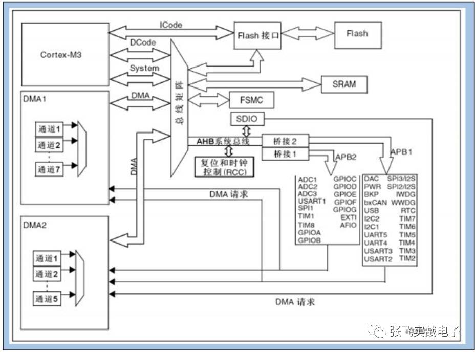
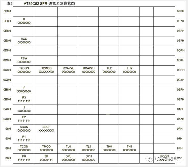
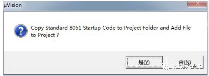
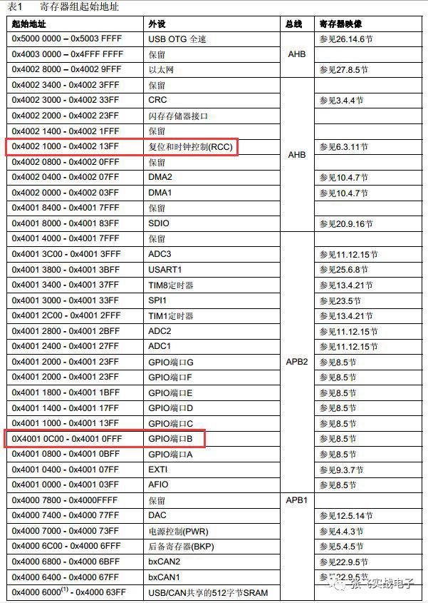
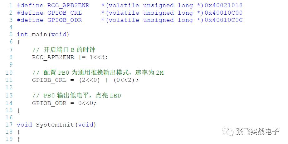
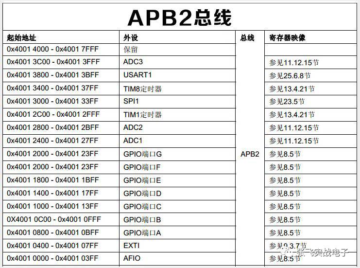
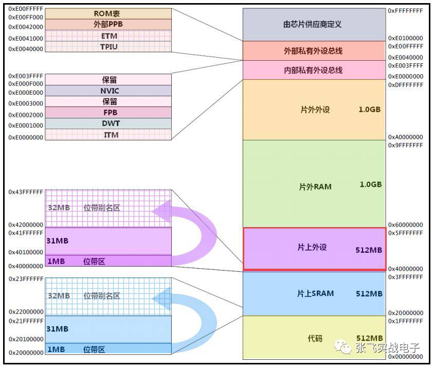
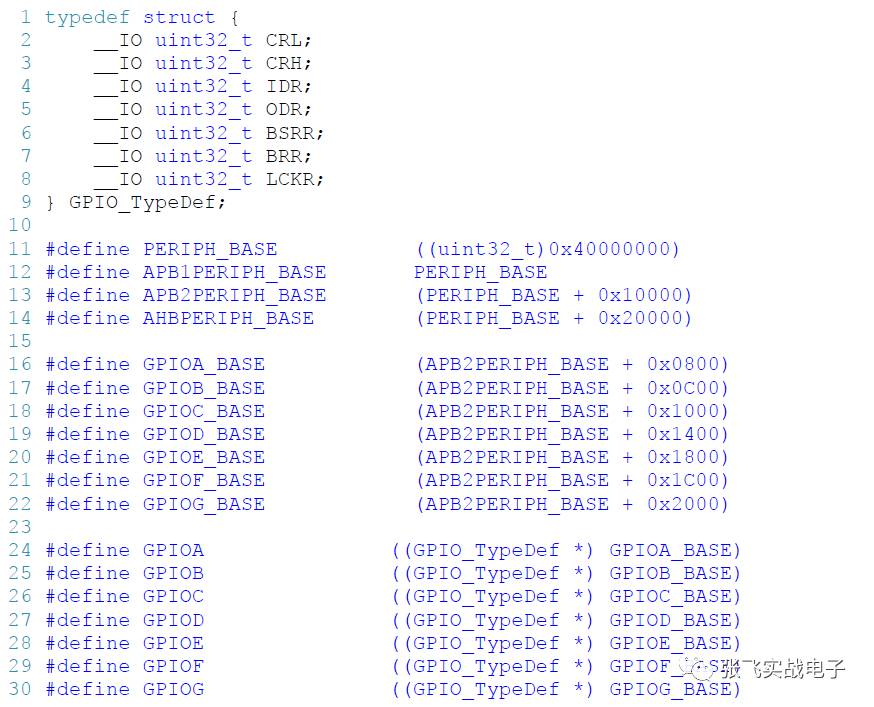
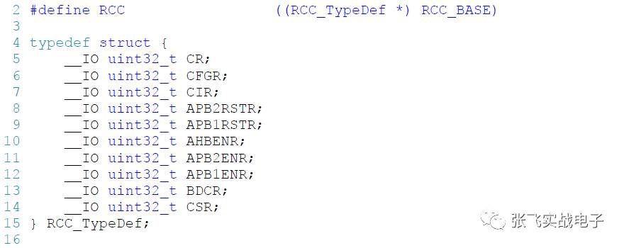
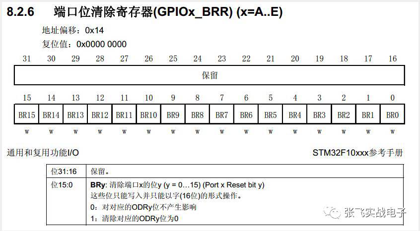
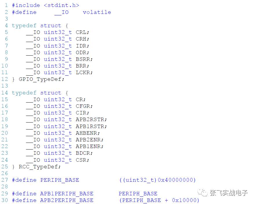
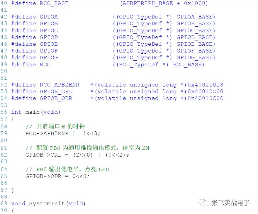
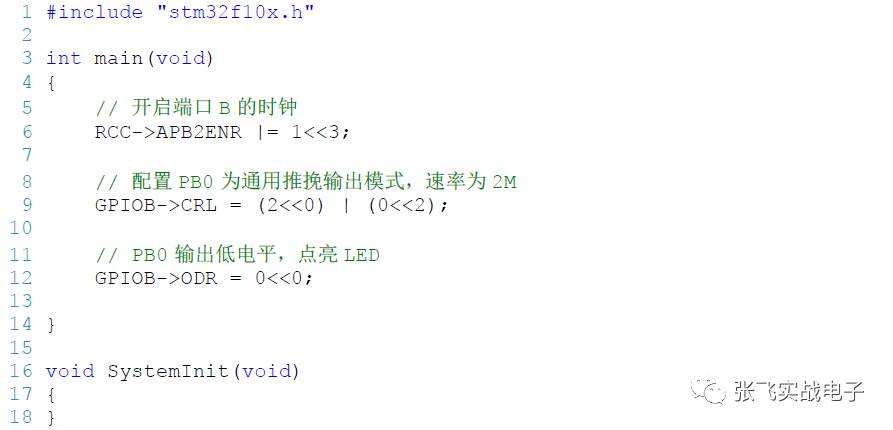
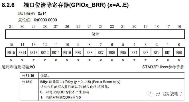
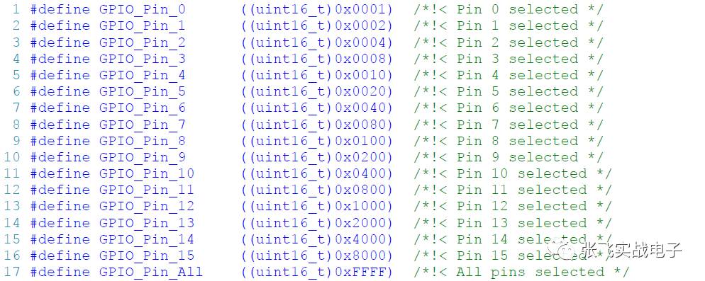
The resources of a 51-bit MCU with an 8-bit kernel are often a maximum of K-100K of flash. 100-Kbytes of RAM, IO, serial port, timer, 8-bit data bus, AD and other simple resources. Goal is determined, single. The structure is simple and the instructions are simple. Easy to understand and operate, these characteristics are also factors that can be deeply rooted in people's hearts. It is still the leading experimental platform for colleges and universities. It is also an application platform for many companies. With the rise of STM32 in the coretex-m3 core in China, it attracted the attention of 51 users. For my understanding when I first entered, I think STM32 is very fast, and flash and ram are big. It can operate the SD card, which is equivalent to the microcontroller's hard disk. Usb function, a thing that has never been seen before 51, can finally communicate with the computer without a serial port. With so many timers, how much PWM control can I do? The 16-bit FSMC bus, which enables high-resolution LCDs, can also be controlled at high speed. No longer, 51 can only use some low-resolution and expensive LCMs such as 12864. Ucos ucgui, which was previously thought of at 51, can be played on STM32. There are a lot of good features, and the controller can easily implement can communication and Ethernet applications that were previously possible to combine circuits. This is the true meaning of the SOC chip in the field of micro-control. Initially into STM32, perhaps the most intimate is the keil used in 51, at 51 it is called keil c51, in arm it is called RealviewMKD-ARM, referred to as MDK, the current version is MDK4.22, the operation method is basically similar to keil. In addition to editing the project, compiling the code, we also use the download and debug. At 51, there may be very few people using the simulation function, because 51 is simple enough, and the brain is often what you see. Downloading directly to the target board is faster for you. So the most common one at 51 is the downloader. But in the arm phase, the resources are complicated and the registers are complicated. There are so many variables, and without an emulator, you will feel so helpless. Therefore, users of coretex-m3 basically have emulators, which are generally divided into ST-LINK ULINK and JLINK, especially JLINK is most popular in China. The reason we all understand, the cost performance of JLINK V8 is the best of these. So, you need to have a JLINK after you get the MDK. It not only supports STM32, it supports the vast majority of ARM chips. 51 When a user first enters STM32, there is a short process in which platform conversion brings confusion, which is a cognitive difference caused by a large change in device type. But adjust it, this discomfort will soon pass. ▶▶1 First look at the 51 and STM32 which are the same type of resources. Depending on how familiar you are with 51, you will see it in the STM32 manual. These tend to be simpler and the easiest to understand. Such as IO line control, and so on. ▶▶2 STM32 Advanced resources often require more energy to understand. This can be learned after getting started, such as USB, SDIO, etc. ▶▶4 Different programming methods, such as 51, can be easily controlled by setting or resetting instructions. In STM32, the function of all resources is related to the operation of the 32-bit register group corresponding to the resource. Therefore, for the setting and operation of resources, it is necessary to operate one or more registers. If multiple instructions are used to control, it will cause reading obstacles, and the code maintenance will be complicated in the future. Therefore, ST Company introduced the concept of library functions. Solve the problem of complex resource operations by executing library functions. ▶▶4 The MDK project of the STM32 routine has a similar program structure. Combined with the manual to see the routines, you will quickly form an understanding of the STM32 routine template. Once this understanding is formed, the remaining code details are like The blank fill you predicted. When you are ready to learn a new platform, then don't hesitate to invest in the embrace of CORETEX-M3. It will make you progress to a new level. Bring you a pleasant technical enjoyment. How to quickly get started with STM32 microcontroller? There is a big god on the Internet saying that if you can 51 SCM and C language can get started STM32, only one day, is it really so fast. This depends on the standard of getting started for yourself. Getting started in my eyes: (provided you have learned 51 microcontrollers and C language) ▶▶1 Know what information to refer to the official to learn, rather than getting caught in a lot of information. ▶▶2 know how to refer to the official manual and the official code to write your own program independently, instead of blindly seeing the code written by others, it feels very good. ▶▶3 Eliminate the fear of STM32 and eliminate the fear of library development. Learning is a happy and fulfilling process. When you read this article, it will work better with the GPIO chapter of the STM32 Chinese Reference Manual, especially when it comes to register descriptions. 51 is an entry-level classic MCU in embedded learning. Because of its simple structure, easy to teach, and can be programmed through serial port without additional emulator, it is widely used in teaching. So many universities are embedded in it. It is still used in teaching. 51.51 Born in the 1970s, it belongs to the traditional 8-bit single-chip microcomputer. Nowadays, after years of baptism, it has both its brilliance and its shortcomings. Today's market products are highly competitive and extremely cost sensitive, and the requirements for MCUs are more demanding: more features, lower power consumption, easy-to-use interfaces and multitasking. Faced with these demands, 51 existing resources seem to be stretched. Therefore, no matter whether it is college teaching or market demand, a new MCU is urgently needed to inject new vitality into this field. Based on the needs of this market, ARM introduced its new 32-bit Cortex-M3 microcontroller core based on the ARMv7 architecture. Shortly thereafter, ST (STMicroelectronics) introduced the MCU-STM32 based on the Cortex-M3 core. With its diversified product line, cost-effective, and easy-to-use library development, STM32 quickly became the brightest star in many Cortex-M3 MCUs. As soon as the STM32 went on the market, it quickly occupied the middle and low-end MCU market. It was favored by the market and engineers, and it was quite a spark. As a qualified embedded engineer, in the face of emerging technologies, we are not deaf to the ears, but to meet the needs of the market as soon as possible, to keep up with the trend of technology. The emergence of STM32 is now a trend, a trend, what we have to do is to catch this fast train and make our technology more competitive. 51 Differences with STM32 architecture We first popularize a concept, what is inside the microcontroller (ie MCU). The most important thing for a person is the brain, and all parts of the body work under the command of the brain. The MCU is very similar to the human body. Simply put, it is composed of one of the most important cores and other peripherals. The kernel is equivalent to the human brain, and the peripherals are like the various functional organs of the human body. Let us briefly introduce the structure of the 51 and STM32. 1 51 System Structure 51 System Block Diagram Figure 1 51 System block diagram We say 51 generally refers to the 51 series of single-chip microcomputers, there are many models, the common ones are STC89C51, AT89S51, of which the most used in China is STC89C51/2, below we will explain with STC89C51, and with 51 abbreviation. Kernel 51 consists of an IP core and on-chip peripherals. The IP core is the CPU in the above figure. The on-chip peripherals are as shown in the above figure: clock circuit, SFR and RAM, ROM, timer/counter, parallel I/O port, serial I/O port, interrupt system. The IP core is connected to the peripheral by the system bus and is 8bits with limited speed. The 51 core was designed by Intel in the 1970s, and the speed is only 12M. The peripherals are added by the IC manufacturer (STC) based on the kernel. Different IC manufacturers will add different peripherals on the core to design Each unique microcontroller. Here intel belongs to the IP core manufacturer, and STC belongs to the IC manufacturer. The same is true for STM32, which we will talk about later. ARM is an IP core vendor, ARM is authorized by ST, and ST has designed an STM32 microcontroller based on the Cortex-M3 core. Peripheral When we were learning 51, there were fewer contacts on the kernel, and the most used ones were on-chip peripherals, which we operated while programming. The registers that are operated during programming are located in the SFR and RAM sections, where the SFR (Special Function Register) occupies 128 bytes (actually only 26 bytes are used, only 26 registers, others belong to the reserved area), and the RAM occupies 128 bits. Bytes, the variables we define in the program are placed in RAM. The SFR and RAM are coincident in address, all in the 80~FF address range, but they are separated in the physical range, so the 51 RAM has 256 bytes. The programmed program is written to the ROM area. The remaining peripherals are the IO ports we are familiar with, serial ports, timers, and interrupts. 2 STM32 system structure STM32 system block diagram Figure 2 STM32 system block diagram Kernel In terms of system architecture, STM32 and 51 are both microcontrollers, which are composed of core and on-chip peripherals. Only the Cortex-M3 core used by STM32 is much more complex and superior than 51. It also supports much more peripherals than 51, and the bus width also rises to 32bit, regardless of speed, power consumption, and peripherals. From the block diagram, there is only one bus for comparing the 51 cores, and the fetch and fetch are shared. There are several bus interfaces inside the Cortex-M3 so that the CM3 can simultaneously address and access (access memory). They are: Instruction memory bus (two), system bus, private peripheral bus. There are two code memory areas that are responsible for accessing the code memory area (ie, the FLASH peripheral), the I-Code bus and the D-Code bus. I-Code is used for indexing, and D-Code is used for table lookup operations, which are optimized for optimal execution speed. The system bus is used to access memory and peripherals. The area covered includes SRAM, on-chip peripherals, off-chip RAM, off-chip expansion devices, and part of the system-level memory area. The private peripheral bus is responsible for accessing a portion of the private peripherals, primarily accessing the debug components. They are also in system level storage. There is also an MDA bus. Literally, DMA is the meaning of data memory access. It is a bridge between the kernel and peripherals. It can access peripherals, memory, transfer without CPU control, and is two-way communication. In short, this guy is a data porter who is fast and not controlled by the boss. This is not available in 51. Peripheral From the block diagram, STM32 has much more peripherals than 51. There are 51 STM32 peripherals such as serial port, timer, and IO port. STM32 also has a number of special peripherals: FSMC, SDIO, SPI, I2C, etc. These peripherals are mounted on the three buses AHB, APB2, and APB1 according to the speed. 3, summary Comparing the two aspects of the kernel and peripherals, STM32 is an upgraded version of the microcontroller. It adapts to the market, drains the trend, and shines in the low-end and mid-range microcontrollers. Learn 51 to learn the STM32 library with registers. When we learn before 51, using a method of programming a register, want to achieve what effect, directly to the registers inside the assignment, the advantage is intuitive, simple and crude, know exactly did what, my heart at ease. The reason why the direct operation register is feasible at 51, I think there are two reasons: ▶▶1 51 The main frequency is not high, the resources are limited, you must pay attention to the efficiency of program execution, and you can only operate the registers directly. The key places have to be compiled, not suitable for firmware libraries. We must know that when we were learning 51 microcontrollers, we used assembly, even the current C programming is not, let alone library function programming. ▶▶2 51 The function is simple and there are not many registers. Domestic most widely popular STC89C52 for example, register all add up to less than 30. According to the function distinction, you can read the back of each register, and the function of each bit of the register can be remembered, and it is done at the time of programming. Nowadays, from the 51 to the STM32 learning, many people still like to follow the 51 learning method. I can't accept the library. When I was learning the library, I was lost in confusion. After a few months of going back and forth, I didn't know if I had learned STM32. Because I was calling the library function in this way, I didn't operate the register at all. The heart is very unreliable. In fact, when you call the library function, there is no doubt in the mind, how is the bottom of the library implemented? Is there no courage to find out the bottom of the library? Finally, when we start tracking the bottom of the library function, we see a bunch of macro definitions, structures, pointers, various file inclusions, and the comments are all in English, is not a jealous. In view of this, I want to summarize the reasons why many beginners are afraid that the library will not use the library for two reasons. ▶▶1 lack of C language knowledge points The macro definition used by the library in implementing the register image, the cast, the structure used in defining the register, the pointer used in the peripheral initialization function, and the C language knowledge used in organizing the header file, etc., in the university course It is rarely involved, and most teachers are basically not talking about it. This knowledge is rarely used in some simple 51 microcontroller programming. Learning microcontrollers, doing embedded development, in fact, 80% of the work is related to C language programming, the remaining 20% ​​of the work is to read a variety of data manuals, familiar with a variety of hardware peripherals. So mastering these basic C language knowledge is a hurdle in embedded learning, and the STM32 library gives us a chance to improve C. Anything that can be found in books, I believe that we can basically learn, many beginners are not smart or diligent, just lack of directional guidance. For this lack of knowledge, we can take a little time to master, and the rest is constantly practicing debugging. Here I recommend a C book "C and Pointer" for everyone. ▶▶2 lack of program architecture design ideas This is more difficult to do, and many people who learn well in C language are more difficult to master. Fortunately, we encountered the STM32 library, which gave us an excellent opportunity to learn and improve the C language. How the entire architecture of the library is built, how the code is written step by step: from the register image, to the encapsulation of the register, and then to the writing of the function, to the driver file corresponding to each peripheral function, which A lot of conditional compilation, the idea of ​​the file, is a nightmare for beginners who have just written a few lines of 51 microcontrollers. However, if you understand the relationship of this series, then you can understand the whole structure of the library, and you don't have to talk about operating the registers in the future. If you don't like to use the library at first, it is taboo for library development, then ask yourself: Is my C language not good enough? The library is a new way of learning, it is a trend, I see it as another experience and promotion with the C language. Whether you use the library, only you have a shiny look. In order to make a smooth transition to library development, at the beginning of STM32 programming, we will show you how to illuminate an LED with 51. How to use STM32 to illuminate an LED by operating the register, and then slowly explain what is the library, let Everyone knows the relationship between the library and the register. 1 illuminate an LED with 51 Before lighting an LED with STM32, let's review how to illuminate an LED with 51. On the hardware, we assume that the 0th bit of the P0 port of the 51 MCU is connected to an LED, and the negative logic is on. If we want to light this LED, we will write this on the code: Here we use the bus operation method, which means that 8 IOs of P0 port operate simultaneously, but only P0^0 is active. In addition to this bus operation method, we also learn the bitwise operation. Using the 51 compiler's keyword sbit, we can define a bit variable: Then LED = 0; the LED is lit, LED = 1; the LED is turned off. In order for the program to appear to be known, we define two macros: The code to illuminate and turn off the LED becomes: The above bus and bit manipulation methods, friends who have learned 51 are very familiar and easy to understand. Then let's talk about a few points of knowledge that are easy to ignore. ▶▶ 1 What is a register? When lighting the LED, we all use the method of operating the register to achieve, then everyone thought about it, what is this register? Why can we operate P0 directly? Before answering the above questions, let's briefly introduce the main components of the 51 MCU, which is good for us to learn other MCUs. Taking the domestic STC89C51 as an example, the MCU is mainly composed of 51 cores, peripheral IP, and bus. The kernel is produced by Intel Corporation. The peripheral IP is added by STC based on the kernel, such as timer, serial port, IO port, etc. The bus is the interface unit used to connect the kernel and peripherals. Intel is an IP nuclear design company here, and STC is an IC design company. There are only a handful of companies in the world that can design IP cores. The ARM company we are very familiar with is an IP core design company. ARM licenses other companies. Other IC companies design unique MCUs on the ARM core. The STM32 we will learn later belongs to the MCU based on the ARM core. . The registers are built into each IP peripheral and are a type of memory used to configure peripheral functions. They are a type of memory and have the address you want to correspond to. Learning C language, we know that to operate these memories, you can use the pointers in the C language to operate these memory-registers with special functions by addressing. For example, if the address corresponding to the P0 port is 0X80, then if we want to modify the content of the memory corresponding to the address 0X80, we can do this according to common sense: But when we compile, the compiler will report an error. In 51, only the SFR and SBIT keywords can be used to implement the register image. The address corresponding to the register cannot be directly manipulated. This is 51 different from STM32. 51 These registers of MCU are located in addresses 80H~FFH, corresponding to 128 addresses, but not every address is valid. There are 21 single-chip microcomputers of 51 series and 26 of 52 series. Others are reserved areas. . Figure 3 51 Register Map ▶▶2 register map In fact, when we are programming, we do not operate the registers by pointers, but directly assign values ​​to the port registers P0 and P1. Then how these peripheral resources establish a one-to-one correspondence with the address (register map definition), which benefits from the two unique keywords of 51: SFR and sbit, other microcontrollers do not, can only use other ways to implement registers Mapping. These two keywords help us to define all the registers, so we can manipulate the registers like one of the normal variables. In fact, the code that lights up the LEDs we mentioned at the beginning should look like this: For convenience, we can write all the register maps in a header file, instead of defining them once for each register. In fact, this work does not need us to do, we will add a header file at the beginning when programming: This header file has been implemented to define all the registers, which are included with the keil and can be found in the installation directory: Keil\C51\INC. This file implements the definition of byte registers and bit registers. ▶▶3 startup file—STARTUP.A51 There is also a startup code, this is also a place that many beginners can easily ignore. For this part, we mainly summarize its functions, and explain the code inside. After the MCU resets, the first execution is the startup file - STARTUP.A51, instead of the main function we usually see. When we create a new 51 project, there will be a prompt: whether to copy the startup code to the current project, we generally choose Yes. Figure 4 Whether to add the startup code The startup code is written in assembly language and mainly implements the following functions: clear internal data memory, clear external data memory, clear external page memory, initialize re-stack and pointer in small mode, initialize re-stack in large mode, and Pointers, initialize restacks and pointers in compact mode, initialize 8051 hardware stack pointers, pass control commands that initialize global variables, or pass commands to the main function when global variables are not initialized. Then the program jumps to the main function and comes to the familiar C world. ▶▶4 summary When explaining the use of 51 to illuminate the LED, we added what is the contents of the register, register mapping, and startup code. These three parts were originally explained in STM32, but considering that everyone already has the basis of 51. And I am familiar with 51, then I will add some content, everyone is naturally not so resistant, and can practice according to the above, and learn more deeply. Then when I explain these things in STM32, everyone will compare and learn, and there is no such jealousness for STM32. 2 Light up an LED with STM32 In contrast to the 51 way to illuminate the LED, we first use the STM32 to illuminate an LED, and then step through the code to build the simplest library function, let us know how the library is built. Before we write the code, let's build a project. It should be noted that although 51 and STM32 are both keil, the MCU is different. The software should be installed in different directories during installation and cannot be installed in the English directory, otherwise it will conflict. We are using keil5, MDK5.15 version here. ▶▶1 New construction Create a new project with KEIL5, put the project in a pre-built folder, and save the project named REG. Then add the startup file in the project directory: startup_stm32f10x_hd.s, which can be found from the KEIL5 installation directory, or from the ST library, and then add the startup file to the project. ▶▶2 startup file—startup_stm32f10x_hd.s The startup file is written in assembly language, and the specific function is similar to the startup file in 51: STARTUP.A51. The startup file of STM32 is mainly implemented: 1. Set the initial SP. 2, set the initial PC = Reset_Handler 3. Set the vector table entry address and initialize the vector table. 4. Call the library function SystemInit to configure the system clock to 72M. SystemInit is defined in the library file system_stm32f10.c. 5. Jump to the label _mian and finally come to the world of C. Here we first remove the details of the branches, focus on the main points, mainly understand the fourth and fifth points, in the 147~155 lines of the startup file, is the reset processing function, the code is as follows: Here we briefly introduce the 10 lines of code. The first line is the program comment, and the comment in the assembly is ";", which is different from the C language. The second line defines a subroutine: Reset_Handler. PROC is a subroutine definition directive. The general usage is: Where NEAR and FAR are attribute words. NEAR attribute (near in the segment): The calling program and subroutine are in the same code segment and can only be called by other programs in the same code segment. FAR attribute (distance between segments): The calling program and the subprogram are not in the same code segment and can be called by programs of the same or different code segments. The third line EXPORT indicates that the subroutine Reset_Handler can be called by other modules. The keyword [WEAK] indicates a weak definition. If the compiler finds a function with the same name defined elsewhere, it will link with the address elsewhere when linking. If the definition is not defined elsewhere, the compiler will not report an error. . The fourth and fifth lines IMPORT indicate that the two labels SystemInit and __main are in other files, and you need to go to other files to find them when linking. SystemInit is implemented in the library file system_stm32f10x.c to initialize a series of clocks for STM32 and set the system clock to 72 MHz. The STM32's clock is more complex than the 51 MCU and requires a series of configurations to achieve stable operation. __main is not actually defined by us. When the compiler compiles, this function is defined whenever the label is encountered. The main function of the function is: responsible for initializing the stack, heap, configuring the system environment, and jumping to user-defined at the end. The main function has since come to the world of C. The sixth line loads the address of SystemInit into register R0. The seventh line of the program jumps to the address execution program in R0, after which the system clock is set to 72 MHz. The eighth line loads the address of _main into register R0. The ninth line of the program jumps to the address execution program in R0. After the execution, it goes to the well-known C world. The tenth line indicates the end of the subroutine. To sum up, the Reset_Handler function performs two function calls, one is SystemInit, sets the system clock to 72M, makes one __main, initializes the system environment, and finally calls the main of C, and then goes to the world of C. When we light the LED, the easiest way is to use the internal LSI clock (8MHZ) as the master clock, without using the external clock LSE. The __main function is generated by the compiler and is responsible for initializing the stack, heap, etc., and finally jumps to the user-defined main() function to the world of C. ▶▶3New main.c Use Notepad to create a new main.c file and put it in the project directory, then add main.c to the project. Now we can start writing the program. Let's write a main function, there is no such thing, it is empty. This is not very similar to writing a 51 program. Now we can compile and see if there is a flaw. At this time, the following error occurred: The error message says that SystemInit is not defined. From the analysis of the startup file, we know that Reset_Handler calls this function to initialize the system clock, and the function is implemented in the library file system_stm32f10x.c. We can rewrite a function like this, and implement the function completely, but for the sake of simplicity, we define a SystemInit empty function in the main file, in order to fool the compiler and remove this error. We will write simple code later on configuring the system clock. At this time, we have no mistakes to compile again, and it is perfectly solved. Another way to do this is to comment out the code for SystemInit in the startup file. The code looks like this: ▶▶4 control IO port Below we explain the difference between STM32's IO and 51 when controlling LEDs. For the description of the registers of the STM32 IO, we can see the eighth chapter of the STM32 Chinese Reference Manual. The IO registers mentioned below are from the second subsection of this chapter: 8.2 GPIO Register Description Level control If the IO port of the MCU is to output 1 and 0, it can be directly assigned without controlling other registers. The STM32 IO port is more complicated. If you want to output 1 and 0, you need to control it by the port output data register ODR. The ODR is: short for the output data register. In STM32, the named names of the registers are in English. Shorthand, it's easy to remember. From the manual we know that the ODR is a 32-bit register, the lower 16 bits are valid, and the upper 16 bits are reserved. The lower 16 bits correspond to IO0~IO16, and you can output low or high level by writing 0 or 1 to the corresponding position. PB0 output low level, the code is as follows: At this time, we will find that there is an error saying that GPIOB_ODR is not defined, but we do not define it. In the 51 MCU, we can assign the value directly to the P0 port. That is because the image of the P0 port register is implemented in the reg51.h header file, which is defined by the 51 unique keyword SFR. STM32 is not the same as 51. There is no SFR. The register image can only be implemented in other ways. Because the register is actually a memory with special functions, we can implement the register image through the macro definition. In fact, this method is also used in the ST library function. From the manual we see that the address offset of the ODR register is: 0CH, which is based on the start address of the port. In STM32, each peripheral has a starting address called the peripheral base address. The peripheral registers are arranged in this order based on the base address, which is similar to the members in the structure. The base address of all peripherals can be found in the 2.3: Memory Image section of Chapter 2: Memory and Bus Architecture in the manual, as follows: Figure 5 STM32 Register Group Start Address The starting address of the GPIOB is: 0X4001 0C00, so that the address of the GPIOB_ODR register can be calculated as: 0X4001 0C00 + 0X0C = 0X4001 0C0C. Now we can define the GPIOB_ODR register, the code is as follows: With this register definition, we can directly operate GPIOB_ODR. Direction control Although the ODR register is configured, the LED cannot be lit at this time because the STM32's IO port is also configured with direction, which is controlled by the port configuration register. The port configuration register is divided into two high and low, one IO port is controlled every 4 bits, so the port configuration low register: CRL controls the lower 8 bits of this IO port, and the port configuration high register: CRH controls the upper 8 bits of this IO port. Among the 4-bit control bits, CNFy[1:0] is used to control the input and output of the port, and MODEy[1:0] is used to control the rate of the output mode, that is, the speed at which the IO level is inverted when outputting. The input has three modes, the output has 4 modes, and we select the universal push-pull output when controlling the LED. There are three modes of output rate: 2M, 10M, 50M, here we choose 2M. Like GPIOB_ODR, we can also calculate the address of GPIO_CRL: 0x40010C00. Then set PB0 to the general push-pull output, and the output rate is 2M. The code is as follows: Clock control When we set the direction of the IO port and input the value in the corresponding output register, we think that the LED can now be lit, but it is still the last step. There are many STM32 peripherals. In order to reduce power consumption, each peripheral corresponds to a clock. These clocks are turned off during system reset. If you want the peripheral to work, you must turn on the corresponding clock. The clocks for all peripherals of the STM32 are managed by a dedicated peripheral called RCC (reset and clockcontrol), which is in Chapter 6 of the STM32 Chinese Reference Manual. The peripherals of STM32 are respectively mounted on three main systems because of different speeds: AHB, APB2, APB1, APB is the high-speed bus, APB2 is the second, and APB1 is again. Therefore, the IO ports are mounted on the APB2 bus and belong to high-speed peripherals. The clock is controlled by the APB2 Peripheral Clock Enable Register (RCC_APB2ENR), where the clock to the PB port is enabled by a '1' on Bit 3 of this register. With ODR and CRL, we can calculate the address of RCC_APB2ENR: 0x40021018. Then enable the clock code of the PB port as follows: If you are careful enough, you will find that although we have opened the port clock, how big is this clock? Where did the clock come from? If we are using a library, then there is a library function SystemInit that will help us set the system clock to 72M. Now that we are not using the library, what is the clock now? The answer is 8M. When the external HSE is not turned on or fails, the system clock is provided by the internal low-speed clock LSI. Now we do not turn on the HSE, so the default clock of the system is LSI=8M. For more in-depth details, we will analyze it in detail later in the RCC clock tree. If you want to try it yourself, look at the RCC peripherals: the clock control register (RCC_CR) and the clock configuration register (RCC_CFGR). Water Controlled the level, configured the direction, turned on the clock, after these three steps, we can finally control an LED. Compared to the 51 direct output level, there are two more steps to control the IO of the STM32: the configuration direction turns the clock on. Compared to the AVR and PIC, there are more steps to turn on the clock. Now we have a complete code to control an LED with STM32: Many people say that learning STM32 is difficult, a bunch of registers, I don't know how to operate, especially those who have just finished 51, I don't know how to overdo it. Here we compare the programming method of 51, and write a simple way to illuminate the LED with the STM32 register, hoping to play a role in attracting jade. Learning STM32 has a controversial point of using registers or libraries, just as programming is better with assembly or with C. In fact, the market is self-determined and the user group explains everything. Although we have lit the LEDs with registers, it looks like the code is very simple, but we don't have to be lucky to use register development in the future.在用寄å˜å™¨ç‚¹äº®LED 的时候,我们是å¦å‘现STM32 的寄å˜å™¨éƒ½æ˜¯32 ä½çš„,在é…置的时候éžå¸¸å®¹æ˜“出错,而且代ç 还很ä¸å¥½ç†è§£ã€‚所以å¦ä¹ TM32 最好的方法是用库,然åŽåœ¨åº“的基础上了解底层,看é所有寄å˜å™¨ã€‚ ä½†æ˜¯å¾ˆå¤šäººå¯¹åº“è¿˜æ˜¯å¾ˆå¿Œæƒ®ï¼Œå› ä¸ºä¸€å¼€å§‹ç”¨åº“çš„æ—¶å€™æœ‰å¾ˆå¤šä»£ç ,很多文件,ä¸çŸ¥é“如何入手。ä¸çŸ¥é“ä½ æ˜¯å¦è®¤åŒè¿™ä¹ˆä¸€å¥è¯ï¼šä¸€åˆ‡çš„æ惧都æ¥æºäºŽè®¤çŸ¥çš„ç©ºç¼ºã€‚æˆ‘ä»¬å¯¹åº“å¿Œæƒ®é‚£æ˜¯å› ä¸ºæˆ‘ä»¬ä¸çŸ¥é“什么是库,ä¸çŸ¥é“库是怎么实现的。 接下æ¥ï¼Œæˆ‘们在寄å˜å™¨ç‚¹äº®LED 的代ç 上继ç»å®Œå–„,把代ç 一层层å°è£…,实现库的最åˆçš„é›å½¢ï¼Œç›¸ä¿¡ç»è¿‡è¿™ä¸€æ¥çš„å¦ä¹ åŽï¼Œä½ 会对库的è¿ç”¨åšåˆ°æ¸¸åˆƒæœ‰ä½™ã€‚这里我们åªè®²å…³äºŽGPIO 库,其他外设的我们直接å‚考库å¦ä¹ å³å¯ï¼Œä¸å¿…自己写。 1 定义外设寄å˜å™¨ç»“构体 上é¢æˆ‘们在æ“作寄å˜å™¨çš„时候,æ“作的是寄å˜å™¨çš„ç»å¯¹åœ°å€ï¼Œå¦‚æžœæ¯ä¸ªå¯„å˜å™¨éƒ½è¿™æ ·æ“作,那将éžå¸¸éº»çƒ¦ã€‚ 我们考虑到外设寄å˜å™¨çš„地å€éƒ½æ˜¯åŸºäºŽå¤–设基地å€çš„å移地å€ï¼Œéƒ½æ˜¯åœ¨å¤–设基地å€ä¸Šé€ä¸ªè¿žç»é€’增的,æ¯ä¸ªå¯„å˜å™¨å 32 个或者16 个å—节,这ç§æ–¹å¼è·Ÿç»“构体里é¢çš„æˆå‘˜ç±»ä¼¼ã€‚所以我们å¯ä»¥å®šä¹‰ä¸€ç§å¤–设结构体,结构体的地å€ç‰äºŽå¤–设的基地å€ï¼Œç»“构体的æˆå‘˜ç‰äºŽå¯„å˜å™¨ï¼Œæˆå‘˜çš„排列顺åºè·Ÿå¯„å˜å™¨çš„顺åºä¸€æ ·ã€‚è¿™æ ·æˆ‘ä»¬æ“作寄å˜å™¨çš„时候就ä¸ç”¨æ¯æ¬¡éƒ½æ‰¾åˆ°ç»å¯¹åœ°å€ï¼Œåªè¦çŸ¥é“外设的基地å€å°±å¯ä»¥æ“作外设的全部寄å˜å™¨ï¼Œå³æ“作结构体的æˆå‘˜å³å¯ã€‚ 下é¢æˆ‘们先定义一个GPIO 寄å˜å™¨ç»“构体,结构体里é¢çš„æˆå‘˜æ˜¯GPIO 的寄å˜å™¨ï¼Œæˆå‘˜çš„顺åºæŒ‰ç…§å¯„å˜å™¨çš„å移地å€ä»Žä½Žåˆ°é«˜æŽ’列,æˆå‘˜ç±»åž‹è·Ÿå¯„å˜å™¨ç±»åž‹ä¸€æ ·ã€‚ 在《STM32 ä¸æ–‡å‚考手册》8.2 寄å˜å™¨æè¿°ç« èŠ‚ï¼Œæˆ‘ä»¬å¯ä»¥æ‰¾åˆ°ç»“构体里é¢çš„7 个寄å˜å™¨æ述。在点亮LED 的时候我们åªç”¨äº†CRL å’ŒODR 这两个寄å˜å™¨ï¼Œè‡³äºŽå…¶ä»–寄å˜å™¨çš„功能大家å¯ä»¥è‡ªè¡Œçœ‹æ‰‹å†Œäº†è§£ã€‚ 在GPIO 结构体里é¢æˆ‘们用了两个数æ®ç±»åž‹ï¼Œä¸€ä¸ªæ˜¯uint32_tï¼Œè¡¨ç¤ºæ— ç¬¦å·çš„32 ä½æ•´åž‹ï¼Œå› 为GPIO 的寄å˜å™¨éƒ½æ˜¯32 ä½çš„ã€‚è¿™ä¸ªç±»åž‹å£°æ˜Žåœ¨æ ‡å‡†å¤´æ–‡ä»¶stdint.h 里é¢ï¼Œæˆ‘们在程åºä¸Šåªè¦åŒ…å«è¿™ä¸ªå¤´æ–‡ä»¶å³å¯ã€‚ å¦å¤–一个是__IO,这个是我们自己定义的,原型是volatile,作用就是告诉编译器ä¸è¦å› 优化而çœç•¥æ¤æŒ‡ä»¤ï¼Œå¿…é¡»æ¯æ¬¡éƒ½ç›´æŽ¥è¯»å†™å…¶å€¼ï¼Œè¿™æ ·å°±èƒ½ç¡®ä¿æ¯æ¬¡è¯»æˆ–者写寄å˜å™¨éƒ½çœŸæ£æ‰§è¡Œåˆ°ä½ã€‚ 关于这两个数æ®ç±»åž‹ï¼Œæˆ‘ä»¬æ·»åŠ å¦‚ä¸‹ä»£ç : 2 外设声明 现在GPIO 寄å˜å™¨ç»“构体已ç»å®šä¹‰å¥½äº†ï¼ŒSTM32F1 系列的GPIO 端å£åˆ†A~G,å³GPIOAã€GPIOB。 . . . . . GPIOG。æ¯ä¸ªç«¯å£éƒ½å«æœ‰GPIO_TypeDef 结构体里é¢çš„寄å˜å™¨ï¼Œæˆ‘们å¯ä»¥æ ¹æ®å„个端å£çš„基地å€æŠŠGPIO çš„å„个端å£å®šä¹‰æˆä¸€ä¸ªGPIO_TypeDef 类型的指针,然åŽæˆ‘们就å¯ä»¥æ ¹æ®ç«¯å£å(实际上现在是结构体指针了)æ¥æ“作å„个端å£çš„寄å˜å™¨ï¼Œç 实现如下: 对于其他外设我们也å¯ä»¥è¿™æ ·æŠŠå¤–设的åå—定义æˆä¸€ä¸ªå¤–设寄å˜å™¨ç»“构体类型的指针,这里我们åªè®²GPIO。 对于æ¯ä¸ªGPIO 的基地å€æˆ‘们å¯ä»¥ä»Žã€ŠSTM32 ä¸æ–‡å‚考手册》2.3 å°èŠ‚:å˜å‚¨å™¨æ˜ åƒä¸æ‰¾åˆ°ï¼Œå¦‚下所示: 图6 APB2 总线外设寄å˜å™¨èµ·å§‹åœ°å€ 3 外设内å˜æ˜ å°„ 讲到基地å€çš„时候我们å†å¼•äººä¸€ä¸ªçŸ¥è¯†ç‚¹ï¼šCortex-M3 å˜å‚¨å™¨ç³»ç»Ÿï¼Œè¿™ä¸ªçŸ¥è¯†ç‚¹åœ¨ã€ŠCortex-M3 æƒå¨æŒ‡å—》第5 ç« é‡Œé¢è®²åˆ°ã€‚CM3 的地å€ç©ºé—´æ˜¯4GB,如下图所示: 图7 CM3 内å˜æ˜ å°„ 我们这里è¦è®²çš„是片上外设,就是我们所说的寄å˜å™¨çš„æ ¹æ®åœ°ï¼Œå…¶å¤§å°æ€»å…±æœ‰512MB,512MB 是其æžé™ç©ºé—´ï¼Œå¹¶ä¸æ˜¯æ¯ä¸ªå•ç‰‡æœºéƒ½ç”¨å¾—完,实际上å„个MCU 厂商都åªæ˜¯ç”¨äº†ä¸€éƒ¨åˆ†è€Œå·²ã€‚STM32F1 系列用到了:0x4000 0000 ~0x5003 FFFF。 ▶▶1 APB1ã€APB2ã€AHB æ€»çº¿åŸºåœ°å€ çŽ°åœ¨æˆ‘ä»¬è¯´çš„STM32 的寄å˜å™¨å°±æ˜¯ä½äºŽè¿™ä¸ªåŒºåŸŸï¼Œè¿™é‡Œé¢ST 设计了三æ¡æ€»çº¿ï¼šAHBã€APB2 å’ŒAPB1,其ä¸AHB å’ŒAPB2 是高速总线,APB1 是低速总线。ä¸åŒçš„å¤–è®¾æ ¹æ®é€Ÿåº¦ä¸åŒåˆ†åˆ«æŒ‚载到这三æ¡æ€»çº¿ä¸Šã€‚从下往上ä¾æ¬¡æ˜¯ï¼šAPB1ã€APB2ã€AHB,æ¯ä¸ªæ€»çº¿å¯¹åº”的地å€åˆ†åˆ«æ˜¯ï¼šAPB1:0x40000000,APB2:0x4001 0000,AHB:0x4001 8000。 这三æ¡æ€»çº¿çš„基地å€æˆ‘们是从《STM32 ä¸æ–‡å‚考手册》2.3 å°èŠ‚—å˜å‚¨å™¨æ˜ åƒå¾—到的:APB1 的基地å€æ˜¯TIM2 定时器的起始地å€ï¼ŒAPB2 的基地å€æ˜¯AFIO 的起始地å€ï¼ŒAHB 的基地å€æ˜¯SDIO 的起始地å€ã€‚ å…¶ä¸APB1 地å€åˆå«åšå¤–设基地å€ï¼Œæ˜¯æ‰€æœ‰å¤–设的基地å€ï¼Œå«åšPERIPH_BASE。 现在我们把这三æ¡æ€»çº¿åœ°å€ç”¨å®å®šä¹‰å‡ºæ¥ï¼Œä»¥åŽæˆ‘们在定义其他外设基地å€çš„时候,åªéœ€è¦åœ¨è¿™ä¸‰æ¡æ€»çº¿çš„基å€ä¸ŠåŠ 上å移地å€å³å¯ï¼Œä»£ç 如下: ▶▶2 GPIO 端å£åŸºåœ°å€ å› ä¸ºGPIO 挂载到APB2 总线上,那么现在我们就å¯ä»¥æ ¹æ®APB2 的基å€ç®—出å„个GPIO 端å£çš„基地å€ï¼Œç”¨å®å®šä¹‰å®žçŽ°ä»£ç 如下: 现在我们把上é¢çš„代ç ç¨å¾®æ•´ç†ä¸‹ï¼Œå¦‚下: 在点亮LED 的时候,我们还开了GPIO 的时钟,用到了RCC 这个外设,现在我们也定义一个RCC 寄å˜å™¨ç»“æž„ä½“ï¼ŒåŠ ä¸Šé‚£äº›åœ°å€å®šä¹‰ï¼Œæ€»ä½“代ç 如下: è·ŸGPIO ä¸åŒçš„是,RCC 这个外设是挂载到AHB 总线上。 现在我们点亮LED 的函数就å˜æˆäº† 对比之å‰çš„代ç 一个用的是结构体,一个用的是å®ï¼Œä»…仅从这三行代ç 看ä¸å‡ºæœ‰å•¥åŒºåˆ«ï¼Œä½†æ˜¯å¦‚æžœè¦æ“作其他寄å˜å™¨çš„时候,用结构体就å¯ä»¥ç›´æŽ¥æ“作,用å®å°±è¿˜è¦ä¸€ä¸ªä¸ªæ‰¾åˆ°å¯„å˜å™¨çš„ç»å¯¹åœ°å€é‡æ–°å®šä¹‰ã€‚ 比如我们è¦æ“作GPIOB çš„BSRR(bit reset register)的时候,用结构体时我们就å¯ä»¥è¿™æ ·æ“作: 这时候PB0 就输出低电平,LED 被点亮。注æ„:BRR 低16 ä½æœ‰æ•ˆï¼Œåªèƒ½ä»¥å—çš„å½¢å¼æ“作,功能是å¤ä½ç›¸åº”çš„IO å£ï¼Œå†™1 清0,写0 没有影å“。 图8 GPIO 端å£ä½æ¸…除寄å˜å™¨ 现在我们å†æ•´ç†ä¸‹ä»£ç ,如下所示: 4 å°ç»“æµç¨‹ 现在我们æ¥æ€»ç»“下上é¢ä»£ç 实现的过程,这个过程也是我们从零开始点亮LED 的过程,代ç 全部由我们自己编写(除了å¯åŠ¨ä»£ç ),æ¯ä¸€è¡Œéƒ½æœ‰æ ¹æœ‰æ®ï¼Œéƒ½å¯ä»¥ä»Žã€ŠSTM32ä¸æ–‡å‚考手册》查到。 â‘ ã€å®šä¹‰ä¸€ä¸ªå¤–设(GPIO)寄å˜å™¨ç»“构体,结构体的æˆå‘˜åŒ…å«è¯¥å¤–设的所有寄å˜å™¨ï¼Œæˆå‘˜çš„排列顺åºè·Ÿå¯„å˜å™¨å移地å€ä¸€æ ·ï¼Œæˆå‘˜çš„æ•°æ®ç±»åž‹è·Ÿå¯„å˜å™¨çš„ä¸€æ ·ã€‚ ②外设内å˜æ˜ 射,å³æŠŠåœ°å€è·Ÿå¤–设建立起一一对应的关系。51 å•ç‰‡æœºä¸ç”¨SFR 实现,STM32 ä¸ç”¨å®å®šä¹‰å®žçŽ°ã€‚ ③外设声明,å³æŠŠå¤–设的åå—定义æˆä¸€ä¸ªå¤–设寄å˜å™¨ç»“构体类型的指针。 â‘£æ“作寄å˜å™¨ï¼Œå®žçŽ°ç‚¹äº®LED。 5 新建头文件stm32f10x.h 为了使代ç 看起æ¥ä¸é‚£ä¹ˆè‡ƒè‚¿ï¼Œæˆ‘们这里引入文件的概念,让ä¸åŒåŠŸèƒ½çš„代ç 放在ä¸åŒçš„文件里é¢ã€‚在main.c 里é¢æˆ‘们åªä¿ç•™main 函数和一些头文件,把其他的å®å®šä¹‰æ”¾åˆ°ä¸€ä¸ªå•ç‹¬çš„文件。 新建一个stm32f10x.h,跟寄å˜å™¨ç›¸å…³çš„代ç 都放在这里,主è¦æ˜¯å¯„å˜å™¨æ˜ åƒï¼Œè·Ÿ51å•ç‰‡æœºé‡Œé¢çš„reg51.h 这个头文件差ä¸å¤šã€‚然åŽæˆ‘们在main.c 里é¢åŒ…å«è¿™ä¸ªå¤´æ–‡ä»¶å³å¯ï¼ŒçŽ°åœ¨æˆ‘们的主函数就å˜æˆè¿™æ ·ï¼š 6 新建tm32f10x_gpio.h 上é¢æˆ‘们在控制GPIO 输出内容的时候控制的是ODR(Output data register)寄å˜å™¨ï¼ŒODR 是一个16 ä½çš„寄å˜å™¨ï¼Œå¿…须以å—çš„å½¢å¼æŽ§åˆ¶ï¼Œç›¸å½“于51 里é¢çš„总线æ“作。 其实我们还å¯ä»¥æŽ§åˆ¶BSRR å’ŒBRR 这两个寄å˜å™¨æ¥æŽ§åˆ¶IO 的电平,下é¢æˆ‘们简å•ä»‹ç»ä¸‹BRR 寄å˜å™¨çš„功能,BSRR è‡ªè¡Œçœ‹æ‰‹å†Œç ”ç©¶ã€‚ BRR:bit reset register 图9 GPIO 端å£ä½æ¸…除寄å˜å™¨ ä½æ¸…除寄å˜å™¨BRR åªèƒ½å®žçŽ°ä½æ¸…0 æ“作,是一个32 ä½å¯„å˜å™¨ï¼Œä½Ž16 ä½æœ‰æ•ˆï¼Œå†™0 没影å“,写1 清0。 现在我们è¦ä½¿PB0 输出低电平,点亮LED,则åªè¦å¾€BRR çš„BR0 ä½å†™1 å³å¯ï¼Œå…¶ä»–ä½ä¸º0,代ç 如下: 这时PB0 就输出了低电平,LED 就被点亮了。 如果è¦PB2 输出低电平,则是: 如果è¦PB3/4/5/6。 . . . . .这些IO 输出低电平呢?é“ç†æ˜¯ä¸€æ ·çš„,åªè¦å¾€BRR 的相应ä½ç½®èµ‹ä¸åŒçš„值å³å¯ã€‚å› ä¸ºBRR 是一个16 ä½çš„寄å˜å™¨ï¼Œä½æ•°æ¯”较多,赋值的时候容易出错,而且从赋值的16 进制数å—我们很难清楚的知é“控制的是哪个IO。这时,我们是å¦å¯ä»¥æŠŠBRR çš„æ¯ä¸ªä½ç½®1 都用å®å®šä¹‰æ¥å®žçŽ°ï¼Œå¦‚GPIO_Pin_0 就表示0X0001,GPIO_Pin_2 就表示0X0004。åªè¦æˆ‘们定义一次,以åŽéƒ½å¯ä»¥ä½¿ç”¨ï¼Œè€Œä¸”还è§å知æ„。 GPIO_pins_define 代ç 如下: 这时PB0 就输出了低电平的代ç å°±å˜æˆäº†ï¼š 为了ä¸ä½¿main 函数看起æ¥å†—余,GPIO_pins_define 的代ç ä¸åº”该放在main 里é¢ï¼Œå› 为其是跟GPIO 相关的,我们å¯ä»¥æŠŠè¿™äº›å®æ”¾åœ¨ä¸€ä¸ªå•ç‹¬çš„头文件里é¢ã€‚ 在工程目录下新建stm32f10x_gpio.h,把GPIO_pins_define 代ç 放里é¢ï¼Œç„¶åŽæŠŠè¿™ä¸ªæ–‡ä»¶æ·»åŠ 到工程里é¢ã€‚这时我们åªéœ€è¦åœ¨main.c 里é¢åŒ…å«è¿™ä¸ªå¤´æ–‡ä»¶å³å¯ã€‚ 7 新建stm32f10x_gpio.c 我们点亮LED 的时候,控制的是PB0 这个IO,如果LED 接到的是其他IO,我们就需è¦æŠŠGPIOB 修改æˆå…¶ä»–的端å£ï¼Œå…¶å®žè¿™æ ·ä¿®æ”¹èµ·æ¥ä¹Ÿå¾ˆå¿«å¾ˆæ–¹ä¾¿ã€‚但是为了æ高程åºçš„å¯è¯»æ€§å’Œå¯ç§»æ¤æ€§ï¼Œæˆ‘们是å¦å¯ä»¥ç¼–写一个专门的函数用æ¥å¤ä½GPIO çš„æŸä¸ªä½ï¼Œè¿™ä¸ªå‡½æ•°æœ‰ä¸¤ä¸ªå½¢å‚,一个是GPIOX(X=A...G),å¦å¤–一个是GPIO_Pin(0...15ï¼‰ï¼Œå‡½æ•°çš„ä¸»ä½“åˆ™æ˜¯æ ¹æ®å½¢å‚GPIOX å’ŒGPIO_Pin æ¥æŽ§åˆ¶BRR 寄å˜å™¨ï¼Œä»£ç 如下: 这时,PB0 输出低电平,点亮LED 的代ç å°±å˜æˆäº†ï¼š åŒæ ·ï¼Œå› 为这个函数是控制GPIO 的函数,我们å¯ä»¥æ–°å»ºä¸€ä¸ªä¸“门的文件æ¥æ”¾è·Ÿgpio有关的函数。 在工程目录下新建stm32f10x_gpio.c,把GPIO 相关的函数放里é¢ã€‚ 这时我们是å¦å‘现刚刚新建了一个头文件stm32f10x_gpio.h,这两个文件å˜æ”¾çš„都是跟外设GPIO 相关的。C 文件里é¢çš„函数会用到h 头文件里é¢çš„定义,这两个文件是相辅相æˆçš„,故我们在stm32f10x_gpio.c 文件ä¸ä¹ŸåŒ…å«stm32f10x_gpio.h 这个头文件。别忘了把stm32f10x.h 这个头文件也包å«è¿›åŽ»ï¼Œå› 为有关寄å˜å™¨çš„所有定义都在这个头文件里é¢ã€‚ 如果我们写其他外设的函数,我们也应该跟GPIO ä¸€æ ·ï¼Œæ–°å»ºä¸¤ä¸ªæ–‡ä»¶ä¸“é—¨æ¥å˜å‡½æ•°ï¼Œæ¯”如RCC 这个外设我们å¯ä»¥æ–°å»ºstm32f10x_rcc.c å’Œstm32f10x_rcc.h。其他外ä¾è‘«èŠ¦ç”»ç“¢å³å¯ã€‚ stm32f10x_gpio.c 文件代ç 如下: 我们还è¦è®°å¾—把void GPIO_ResetBits()在stm32f10x_gpio.h 里é¢å£°æ˜Žä¸‹ï¼Œè¿™æ ·å…¶ä»–文件åªè¦åŒ…å«stm32f10x_gpio.h 这个头文件就å¯ä»¥ä½¿ç”¨GPIO_ResetBits()这个函数了。以åŽä¸è®ºæ–°å¢žåŠ 了什么函数都应该在自己的头文件下声明,这是个C è¯è¨€çš„常识问题。 点亮LED 会了,那关é—LED 怎么办,我们å¯ä»¥æŽ§åˆ¶BSRR 这个寄å˜å™¨æ¥å®žçŽ°ï¼Œè¿™é‡Œæˆ‘就直接写代ç 了: 先写一个GPIO 端å£ç½®ä½å‡½æ•°ï¼Œæ”¾åˆ°stm32f10x_gpio.c 文件ä¸ï¼ŒåŒæ ·åœ¨ stm32f10x_gpio.h 头文件声明。 PB0 输出高电平,关é—LED,代ç 如下: Dynojet Dyno,Dynamometer For Sale,Dyno Motor,Dyno Machine GALOCE (XI'AN) M&C TECHNOLOGY CO., LTD. , https://www.galoce-meas.com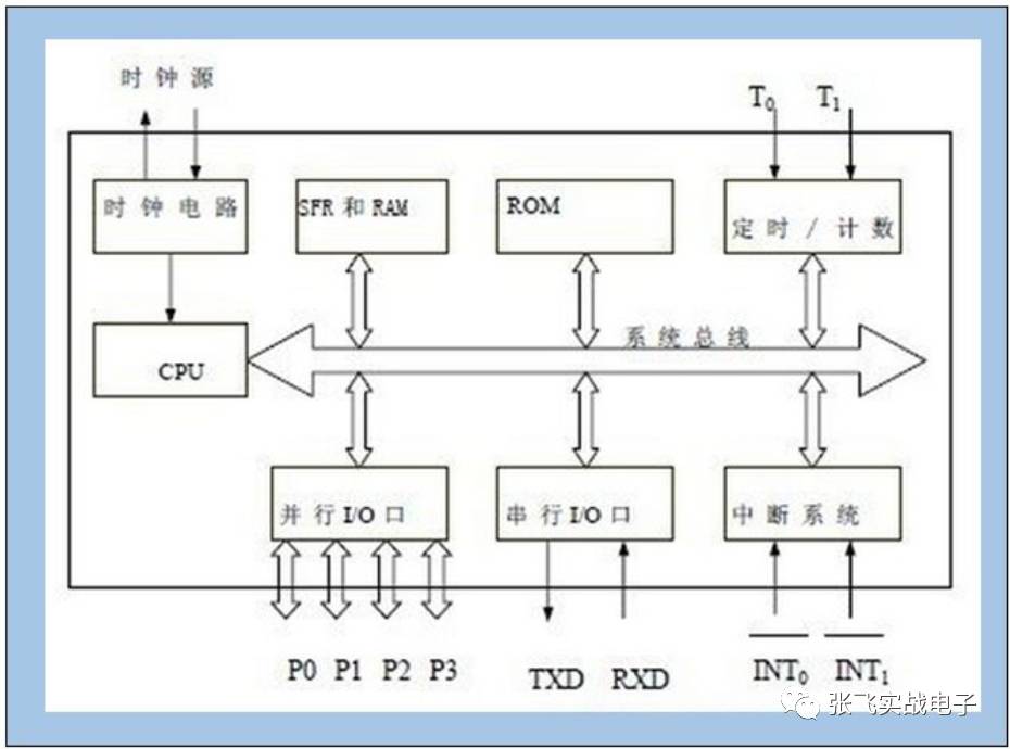





















51 MCU engineers to jump to stm32 method
What you may have been learning or doing before is a 4-bit or 8-bit microcontroller, such as a 51-class microcontroller. Because 51 is so deeply rooted in people's minds, you can easily get a lot of learning materials about him. In the bookstore, 51 kinds of books and textbooks are even placed on several shelves. The most popular development board on a certain treasure must be 51 development boards, rarely Which embedded engineer or student has avoided 51 and went directly to other platforms. We learned the concept of MCU from 51 and learned the concept of control. But today, 51's low cost, easy to use, is no longer dominant. In contrast, the current application in the field of micro-control, the resource requirements for MCU are getting higher and higher, 51 is getting more and more unsuitable.