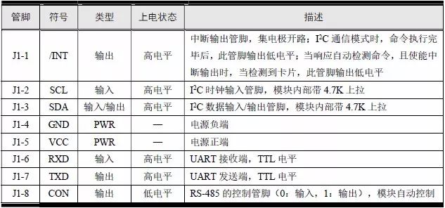
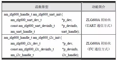
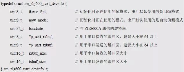
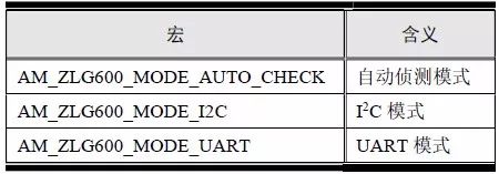
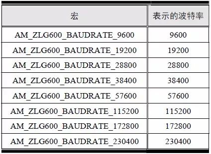
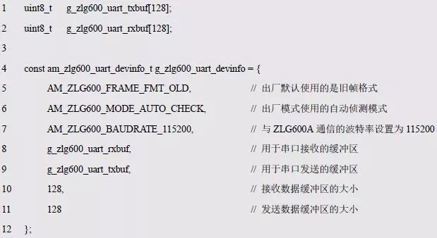
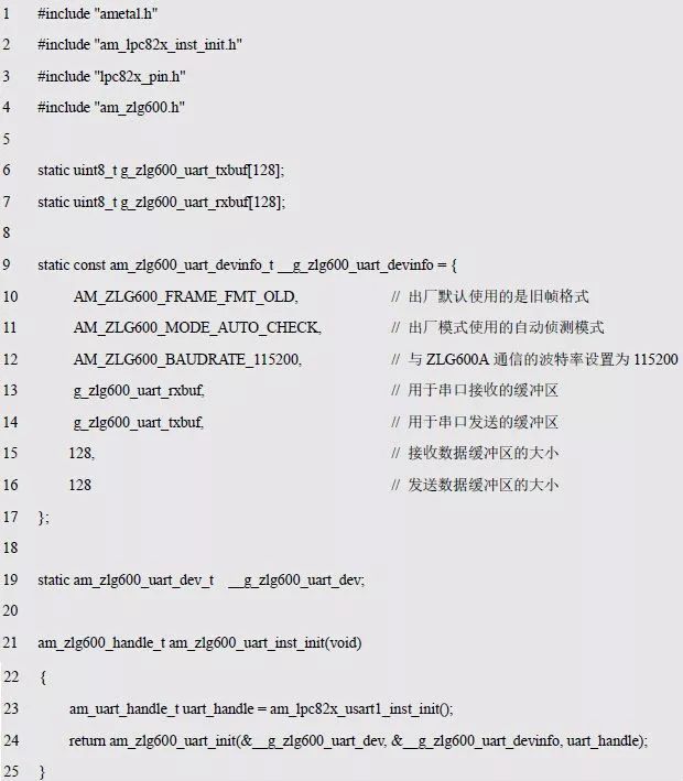
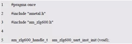
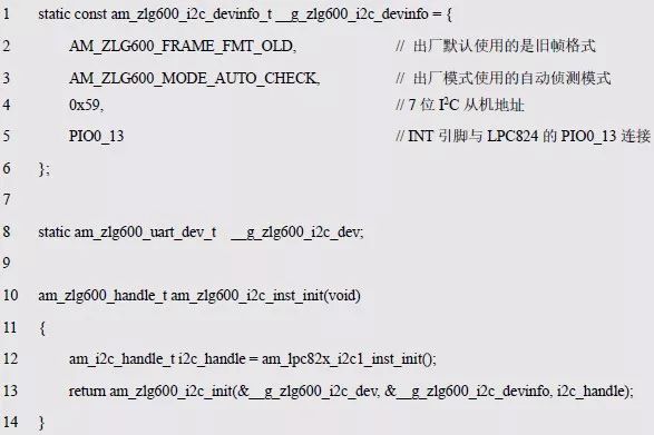
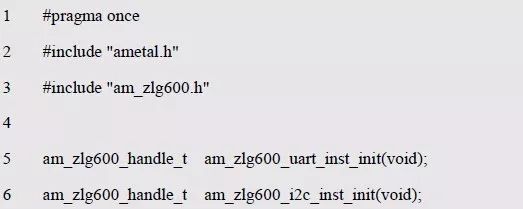
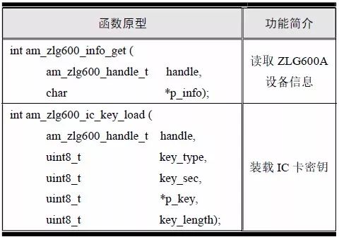
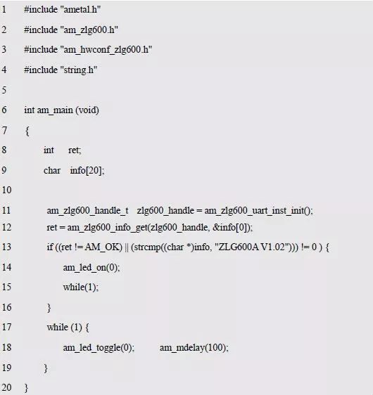
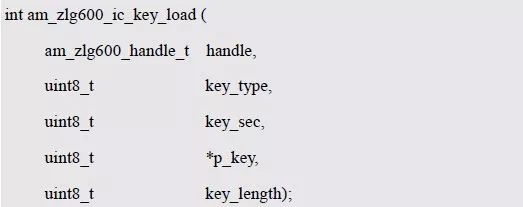
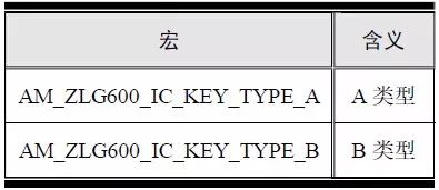
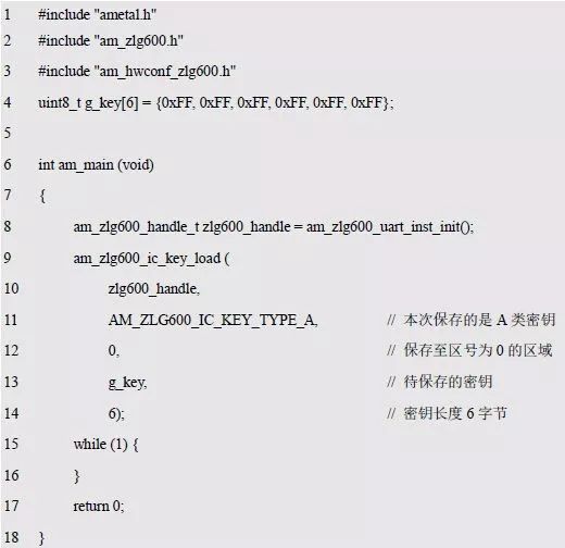
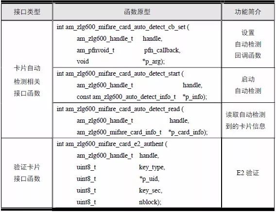
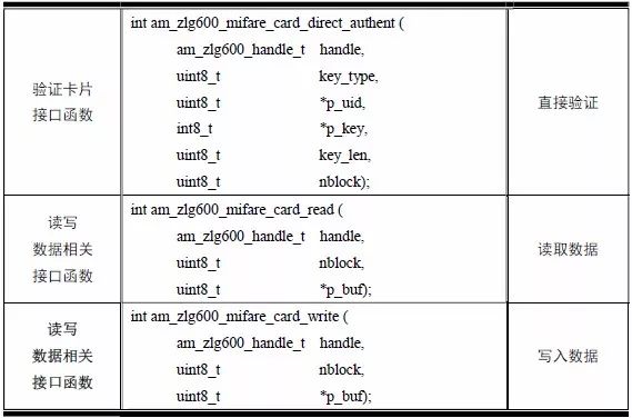
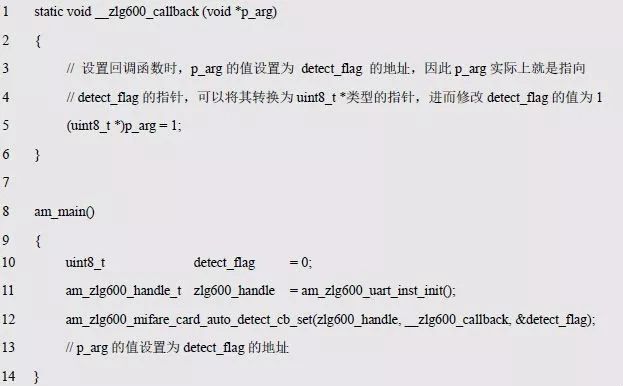
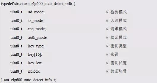
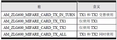
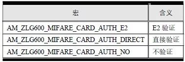
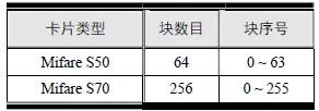
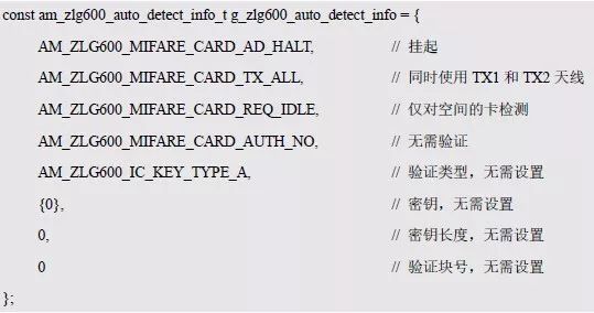
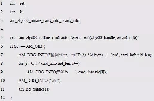
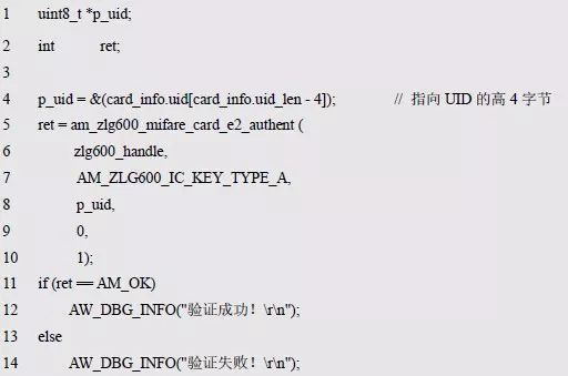
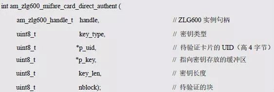
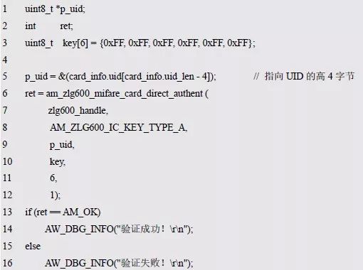
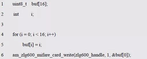
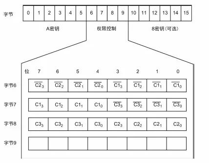
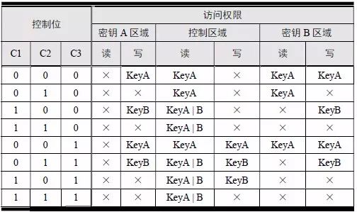
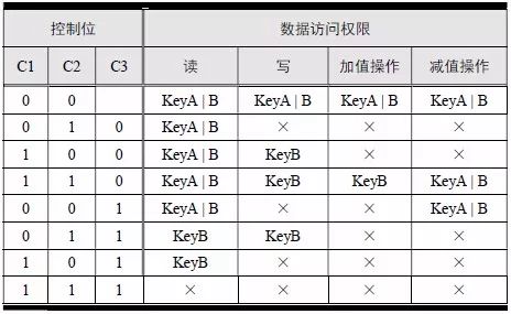
> > > 6.4.1 Basic functions The ZLG600A is a 14443-compliant 13.56MHz read/write card module from ZLG. It supports Plus CPU, Mifare Desfire CPU card, Mifare 1 S50/S70, Mifare 0 ultralight, Mifare Pro card, and ISO7816 protocol read/write contact IC card. It can carry two antennas to meet the multi-card read and write requirements of different positions, and the number of connected slaves is up to 127, supporting I2C , UART, RS-232C, RS-485 interfaces. With active detection card entry function, when the card is detected, an interrupt is generated and the data is output through the serial port and I2C . The ZLG600A series read/write card module selection guide is detailed in Table 6.18. The power supply voltage is 5V and the average current is 77mA. The TypeA, TypeB and PLUS CPU card reading distances are 7.5cm, 4cm and 5cm respectively. Table 6.18 Selection Guide Table Since RS-232C and RS-485 communicate with the UART in exactly the same way, only some conversion circuits have been added to the hardware, so it will not be described later. Only I2C and UART communication methods are introduced here. The pin meanings are shown in Table 6.19. Table 6.19 Communication Interface Definition Note: The square pad is the 1st pin, the 3.3V module J1-5 is connected to the 3.3V power supply, and the 5V module J1-5 is connected to the 5V power supply. When using UART communication, only connect the power pin and the TXD and RXD pins in J1. The other pins are left floating, and the USART0, USART1 or USART2 of the LPC824 is connected to the ZLG600A. When using I2C communication, you need to connect the power pins in J1 and the SCL and SDA pins. Since the I2C slave cannot actively send data to the I2C master, the INT pin is required for the slave to notify the host to process the transaction. The other unused pins are connected to the high level by a 10K pull-up resistor to connect the I2C 0, I2C 1, I2C 2 or I2C 3 of the LPC824 to the ZLG600A. Note: The SCL and SDA modules have pull-up resistors inside, and no external pull-up resistors are required when using I2C communication. > > > 6.4.2 Initialization AMetal has provided the ZLG600A driver function, which must be initialized before using other functions. The initialization function is shown in Table 6.20. Table 6.20 ZLG600A Initialization Interface Function Initializing the ZLG600A is intended to obtain the ZLG600A instance handle. Although the initialization function is different, the return value is the instance handle of ZLG600A. The instance handle will be used as the argument of the other function interface function handle. Therefore, regardless of whether the I2C or UART communication method is selected, the application is independent of the specific communication method as long as it is programmed based on the instance handle. Even if the underlying communication method changes, you only need to change the initialization function when you get the instance handle, and the application "one line of code" does not need to be modified. 1. UART initialization When using UART, its initialization function prototype is: P_dev is a pointer to an instance of type am_zlg600_uart_dev_t; P_devinfo is a pointer to the instance information of the am_zlg600_uart_devinfo_t type. (1) Example The definition of the am_zlg600_uart_dev_t type (am_zlg600.h) is as follows: Where g_zlg600_uart_dev is a user-defined instance whose address is passed as an argument to p_dev. (2) Instance information The example information mainly describes the information about the ZLG600A when using UART communication, including UART buffer information, baud rate and other information. Its type am_zlg600_uart_devinfo_t is defined (am_zlg600.h) as follows: The instance information mainly includes the frame format, ZLG600A mode, baud rate and buffer information. Frame format Frame_fmt indicates the frame format used by the ZLG600A during initialization. To be compatible with earlier products, the ZLG600A supports the new frame format and the old frame format. The corresponding macros are shown in Table 6.21. After the initialization is completed, the frame format used by the ZLG600A can be modified by the corresponding interface function. However, during initialization, you need to know the frame format currently used by the ZLG600A. The default frame format used by the factory is the old frame format, and the value of frame_fmt is set to: AM_ZLG600_FRAME_FMT_OLD. Table 6.21 Macros corresponding to the frame format (am_zlg600.h) Note: If the frame format used by the subsequent related function interface function is replaced after the initialization is completed (such as replacing the old frame format with the new frame format), then the next time the system starts to call the ZLG600A initialization function, you need to ensure the frame_fmt member. The value is the updated frame format (such as the new frame format). ZLG600A mode Now_mode is the mode used for initialization. The ZLG600A supports three modes: auto detect mode, I2C mode, and UART mode. The corresponding macros are shown in Table 6.22. The factory default is auto detect mode. Table 6.22 Macros corresponding to the mode (am_zlg600.h) Note: In the auto-detection mode, in order to use UART communication, Host needs to send 0x20 twice in succession (more than 30us for two time intervals), so that ZLG600A can detect the effective baud rate, which will make the cost of ZLG600A initialize every time. Longer time. Therefore, after this initialization is completed, the mode is fixed to the UART mode by the subsequent interface function. After updating the mode, the next time the system calls the ZLG600A initialization function, ensure that the value of the now_mode member is the updated mode (such as UART mode). In the auto detect mode, both the UART and I2C interfaces are in the receive state. If the ZLG600A detects a valid baud rate from the UART communication line (requires the Host to send 0x20 twice in succession and the time interval is more than 30us for the ZLG600 to detect the effective baud rate), the module uses the UART communication mode; If the module receives a matching slave address from the I2C bus, the module uses the I2C communication method. As long as one of the interfaces receives valid data first, the module will communicate with the host in this way and shut down the other interface. In the UART communication mode, the communication interface is fixed to the UART, and the I2C interface is closed. The host does not need to send the 0x20 twice continuously to detect the ZLG600A baud rate. In the I2C communication mode, the UART interface is closed. After the initialization is completed, the mode used by the ZLG600A can be modified by the corresponding interface function. However, during initialization, you need to know the mode currently used by the ZLG600A. The factory default mode is auto detect mode, and the value of now_mode is set to: AM_ZLG600_MODE_AUTO_CHECK. Baud rate Baudrate is the UART baud rate. The macro definition of baud rate is shown in Table 6.23. In the auto detect mode, you can select any valid baud rate in the table, and the ZLG600A will automatically detect the baud rate used. If in UART mode, the baud rate will be a fixed value, which is the baud rate used when configuring the ZLG600A in UART mode. Table 6.23 Supported UART baud rate corresponding macro (am_zlg600.h) Since the factory default mode is auto detect mode, this value is any valid baud rate. If the baud rate is 115200, the value is AM_ZLG600_BAUDRATE_115200. Buffer information When UART mode communication is selected, both transmit and receive require a buffer to hold data to improve the efficiency of data processing and to ensure that received data is not lost due to transactions being processed. The size of the buffer is specified by the user according to the actual situation. It is recommended to be more than 64 bytes, and is generally set to 128 bytes. P_uart_rxbuf and rxbuf_size describe the first address and size of the receive buffer, and p_uart_txbuf and txbuf_size describe the first address and size of the transmit buffer. If a 128-byte buffer is set for transmission and reception, it is defined as follows: Where g_zlg600_uart_txbuf[128] is used for sending user-defined array space, acting as a send buffer whose address (array name g_zlg600_uart_txbuf or first element address & g_zlg600_uart_txbuf[0]) is the value of the p_uart_txbuf member in the instance information, the array size ( Here is 128) as the value of the txbuf_size member in the instance information. Similarly, g_zlg600_uart_rxbuf[128] acts as a receive buffer with the address as the value of the p_uart_rxbuf member in the instance information and the array size as the value of the rxbuf_size member in the instance information. Based on this, the instance information is defined as follows: (3) UART handle uart_handle If the USART1 of the LPC824 is selected to communicate with the ZLG600A, the UART handle can be obtained by the USART1 instance initialization function am_lpc82x_usart1_inst_init() of the LPC82x. which is: The obtained UART handle can be passed directly as an argument to uart_handle. (4) Example handle The return value of the ZLG600A initialization function am_zlg600_uart_init() is the handle of the ZLG600A instance, which will be the argument of the first parameter of the other function interface. Its type am_zlg600_handle_t(am_zlg600.h) is defined as follows: If the return value is NULL, the initialization fails; if the return value is not NULL, a valid handle is returned. Based on the modular programming idea, the definitions of the initialization related instances, instance information, etc. are stored in the corresponding configuration file, and the instance initialization function interface is extracted through the header file. The program examples of the source file and the header file are respectively shown in the program list 6.98 and the program. Listing 6.99. Listing 6.98 ZLG600A (serial communication) instance initialization function implementation (am_hwconf_zlg600.c) Listing 6.99 ZLG600A (Serial Communication) Instance Initialization Function Declaration (am_hwconf_zlg600.h) Subsequent only need to use the parameterless instance initialization function to get the instance handle of ZLG600A. which is: 2. I2C initialization When using I2C communication, the initialization function prototype is: P_dev is a pointer to an instance of type am_zlg600_i2c_dev_t; P_devinfo is a pointer to the instance information of the am_zlg600_i2c_devinfo_t type. (1) Example The definition of the am_zlg600_i2c_dev_t type (am_zlg600.h) is as follows: Where g_zlg600_i2c_dev is a user-defined instance whose address is passed as an argument to p_dev. (2) Instance information The example information mainly describes the information about the ZLG600A when using I2C communication, including information such as I2C buffer information and baud rate. The definition of its type am_zlg600_i2c_devinfo_t (am_zlg600.h) is as follows: The instance information mainly includes frame format, ZLG600A mode, 7-bit I2C slave address and interrupt pin information. The meaning of frame_fmt is the same as when using UART communication mode. For the factory-set module, the value of frame_fmt should be set to: AM_ZLG600_FRAME_FMT_OLD. The meaning of now_mode is the same as when using UART communication mode. For the factory-set module, the value of now_mode should be set to: AM_ZLG600_MODE_AUTO_CHECK. After this initialization is completed, if the mode is fixed to I2C mode through the subsequent interface function. Then, the next time the system starts to call the ZLG600A initialization function, you must ensure that the value of the now_mode member is the updated I2C mode. Slv_addr is the 7-bit I2C slave address of the ZLG600A. The factory default value is 0x59. The data sheet describes 0xB2. The value is 8-bit address. If the bit is shifted to the right, the value indicating the read/write direction is removed. 0x59. After the initialization is completed, if the I2C address is modified by the subsequent interface function. Then, the next time the system starts to call the ZLG600A initialization function, you must ensure that the value of the slv_addr member is the updated I2C address. Int_pin is the pin number of the ZLG600A's INT pin connected to the actual microcontroller (such as the LPC824). For example, if PIO0_13 of LPC824 is selected and connected to the INT pin of ZLG600A, the value should be set to PIO0_13. Based on this, the instance information is defined as follows: (3) I2C handle i2c_handle If I2C 1 of LPC824 is selected to communicate with ZLG600A, the I2C handle is obtained by the I2C 1 instance initialization function am_lpc82x_i2c1_inst_init() of LPC82x. which is: The obtained I2C handle can be passed directly as an argument to i2c_handle. (4) Example handle Am_zlg600_i2c_init() has the same return value as am_zlg600_uart_init(), which is the handle of the ZLG600A instance, which will be the argument to the first parameter of the other function interface. If the return value is NULL, the initialization fails; if the return value is not NULL, a valid handle is returned. Based on the modular programming idea, the definitions of initialization related instances, instance information, etc. are stored in the corresponding configuration file, and the instance initialization function interface is extracted through the header file. The program examples of the source file and the header file are respectively shown in the program list 6.100 and the program. Listing 6.101. Listing 6.100 Adds an instance initialization function for the I2C communication method of the ZLG600A (am_hwconf_zlg600.c) Listing 6.101 am_hwconf_zlg600.h file content update Subsequent only need to use the parameterless instance initialization function to get the instance handle of ZLG600A. which is: > > > 6.4.3 Device Control Class Interface Function The ZLG600A supports a variety of IC cards, such as Mifare S50/S70, ISO7816-3, ISO14443 (PICC), PLUSCPU cards, etc. Each card has a corresponding command. Commands and interface functions are basically one-to-one correspondence. ZLG600A has many commands, which are divided into the following five categories: device control commands, Mifare S50/S70 card commands, ISO7816-3 commands, and ISO14443 (PICC) cards. Command and PLUS CPU card class commands. The device control interface function is not directly related to the specific card. It is mainly used to directly operate the ZLG600A. For example, obtain the device information of the ZLG600A and store the IC card key. For details, see Table 6.24. Table 6.24 ZLG600A Device Control Class Interface Function (am_zlg600.h) 1. Read device information This function is intended to obtain basic information of the ZLG600A, including product information and version information, and the obtained information is a string, for example, "ZLG600A V1.00". Its function prototype is: P_info is a pointer to get information. Since the string length is 20 bytes, you need to provide a memory space of 20 bytes in length to store the obtained information. If the return value is AM_OK, the information is successful, otherwise it fails. For the sample program, see Listing 6.102. Listing 6.102 Reading the ZLG600A Device Information Sample Program Assuming that the UART communication mode is selected, the instance handle of the ZLG600A can be obtained using the am_zlg600_uart_inst_init() instance initialization function. It also contains the standard C header file string.h. It is convenient to use the strcmp() function to determine whether the string is "ZLG600A V1.00"? Since the ZLG600A V1.00 module is used this time, the information obtained must be “ZLG600A V1.00â€. If you are using a different model or version of the module, you should pay attention to the string of comparison information, otherwise the results will be unequal even if the information is successfully read. 2. Load IC card key The data stored in the card is encrypted, and the data must be read and written after successful verification. Verification is to compare the key provided by the user with the key stored in the card. Only the same is considered to be successful. The ZLG600A provides an E2PROM for storing the key for card verification. The function of loading the IC card key is to store the key in the specified E2PROM storage area. The function prototype is: The key_type is a key type, and the keys are generally classified into two types, which are TypeA and TypeB, respectively. The corresponding macros are shown in Table 6.25. ZLG600A can save 16 groups of type A keys and 16 groups of type B keys. Table 6.25 Key Type (am_zlg600.h) Note: There are two types of keys. It is because there are two types of keys in the actual card. The two types of keys can be used for more convenient management. For example, after TypeA authentication succeeds, only TypeA can be read. Can be written, but the permissions can be customized. Key_sec is the saved area code. Since the ZLG600A can store 16 types of Class A keys and 16 types of B keys, there are 16 areas for each type, and the corresponding area code is 0 ~ 15. P_key points to the buffer of the actual key to be saved, key_length is the length of the key, and the maximum length of the key is 16 bytes. A sample program for saving a set of 6-byte Type A keys to area code 0 is shown in Listing 6.103. Listing 6.103 Load Key Sample Program When the card needs to be verified later, only the E2PROM area number 0 of the key storage is required, and the key need not be sent to the ZLG600A. > > > 6.4.4 Operation interface function The Mifare card is an A-type card conforming to the ISO14443 standard. The interface function is shown in Table 6.26. Table 6.26 Mifare S50/S70 Interface Functions (am_zlg600.h) Frequently used bus cards, room cards, water cards and meal cards are all Mifare cards. For example, S50 and S70, the difference is in the difference in capacity. S50 is 1Kbyte, a total of 16 sectors, 4 blocks per sector, 16 bytes each. S70 is 4Kbyte, a total of 40 sectors, the first 32 sectors each block 4 blocks, each block of 16 bytes, the last 8 sectors each block of 16 blocks, each block of 16 bytes. 1. automatic detection Set automatic detection callback function When a card is close to the ZLG600A, the user-set callback function will be called automatically to read the information about the card, so you need to set a callback function first. Its function prototype is: Where pfn_callback is a pointer to a callback function and p_arg is a parameter to the callback function. If AM_OK is returned, the setting is successful, otherwise it fails. For the sample program, see Listing 6.104. Listing 6.104 Setting up an automatic detection callback function sample program A detect_flag variable is defined in the program to indicate whether a card has been detected. If the initial value is 0, no card is detected. When setting the auto-detect callback function, use its address as the p_arg argument to the callback function. So in the callback function, p_arg is essentially a pointer to detect_flag, with which the detect_flag is set to 1, indicating that the card is currently detected. Start automatic detection When the callback function is set, automatic detection can be initiated. Its function prototype is: Where p_info is a pointer to the information for automatic detection, and its type am_zlg600_auto_detect_info_t is defined as follows: The information structure includes information related to detection mode, antenna mode, request mode, and key verification. Detection mode Ad_mode indicates the detection mode used to configure the detection related actions. Whether the card is suspended when the card is detected, and if the value of ad_mode is set to AM_ZLG600_MIFARE_CARD_AD_HALT(am_zlg600.h), the card is suspended after detecting the card once, and subsequent detection will ignore the card. card. If you need to check the card again, you must move the card away from the ZLG600A and then close it to be effective. If the value of ad_mode is set to 0, the card will not be suspended, and each time an automatic detection can detect a close card. A simple example may be easier to understand. When the bus card is used normally, when the card is close to the card reader, the card will be deducted once and the card is successfully swiped. If the bus card does not leave the card reader, it will not be charged again. At this time, the card has been suspended by the card reader and will not be recognized again. If you leave the bus card close to the card reader and you are close again, you may be charged again. When the value of ad_mode is set to AM_ZLG600_MIFARE_CARD_AD_HALT, you can avoid repeatedly detecting the same card. Antenna mode Tx_mode Sets the working mode of the antenna. ZLG600A has 2 antennas TX1 and TX2. There are 4 working modes: TX1 only, TX2, TX1 and TX2 are used alternately, TX1 and TX2 are used simultaneously, and the value of tx_mode corresponding to each mode is macro. The definition is detailed in Table 6.27. Table 6.27 Antenna working mode (am_zlg600.h) Request mode Req_mode indicates the request mode, that is, whether all cards are detected or only idle cards are detected. The corresponding value macro definition is shown in Table 6.28. Generally, only the idle card is detected. Table 6.28 Request Mode (am_zlg600.h) Key verification Since most cards read a piece of data when a card is detected, the read data can be used as an additional function for automatic detection. That is, when a card is detected, 1 block (16 bytes) of data is automatically read. Since authentication is required before reading data, it is necessary to specify key verification related information when starting automatic detection. The so-called key verification is to compare the key provided by the user with the key stored in the card. Only the equivalent can verify the success. Auth_mode specifies three authentication modes, which correspond to the macro table 6.29. Table 6.29 Verify Mode (am_zlg600.h) If you do not need to read the data when the card is automatically detected, you should set the value of auth_mode to AM_ZLG600_MIFARE_CARD_AUTH_NO. Since the values ​​of the four members key_type, key[16], key_len, and nblock in the information structure are not used, no setting is required. If you need to read data, you must set auth_mode to AM_ZLG600_MIFARE_CARD_AUTH_E2 or AM_ZLG600_MIFARE_CARD_AUTH_DIRECT, the main difference is that the verification key is stored in a different location. If "direct authentication" (AM_ZLG600_MIFARE_CARD_AUTH_DIRECT) is used, the key [16] of the information structure contains the actual key, and key_len indicates the length of the key. If the "E2 Verification" (AM_ZLG600_MIFARE_CARD_AUTH_E2) mode is used, the verification key is stored in the E2PROM of the ZLG600A. At this time, the key [16] of the information structure uses only the first element key[0], which is the area code (0 ~ 15) of the key in the E2PROM. For automatic detection, the key in the corresponding area code of the E2PROM in the ZLG600A will be used for verification. Key_len represents the length of the key. Obviously, if you use "E2 Authentication", you need to make sure that you have used am_zlg600_ic_key_load() to store the key in the corresponding area of ​​the E2PROM in the ZLG600A. The nblock in the information structure specifies the block to be verified, that is, the block in which the data is read, and the data can be read only after the block is successfully verified. The number of blocks included in the Mifare S50 and Mifare S70 cards is detailed in Table 6.30. Table 6.30 Number of blocks of common cards (am_zlg600.h) Assuming that no data needs to be read, the automatic detection information can be defined as follows: After defining the relevant information, you can use the startup function to initiate automatic detection, namely: Read card information After the automatic detection is started, if the previously registered callback function is called, indicating that the card is detected, the interface can be used to read the card information. Its function prototype is: Where p_card_info is a pointer to the card information and is used to obtain card information. The type of card information am_zlg600_mifare_card_info_t(am_zlg600.h) is defined as follows: The information structure includes information related to the antenna driving mode, the card unique serial number, and the read data. Antenna drive mode Tx_mode indicates the driving mode of the antenna. When the automatic detection is started, there are four modes of the antenna: only TX1, only TX2, TX1 and TX2 are used alternately, and TX1 and TX2 are used simultaneously. If the mode used to initiate auto-detection is alternately used for TX1 and TX2, then this value will be set to the antenna from which the card was actually detected. The values ​​that tx_mode may be set are shown in Table 6.31. Table 6.31 Read antenna drive mode (am_zlg600.h) When TX1 and TX2 are used simultaneously, it is impossible to distinguish the antenna from which the card is specifically detected. Slice unique serial number Each card has a unique serial number, the UID. The UIDs of all cards are different. The card has three serial number lengths: 4 bytes, 7 bytes, and 10 bytes. Uid_len indicates the length of the read UID, and uid[10] stores the read UID (the number of bytes). Read data When the automatic detection is started, the verification information related to the reading of the card data is specified. If the auth_mode is not AM_ZLG600_MIFARE_CARD_AUTH_NO, and the corresponding key is correct, the verification is successful, and the block specified by the nblock member of the information structure when the automatic detection is started is read ( The data specified by the nblock of the information structure. The read data is stored in the card_data[16] array. The sample program for reading the card information is shown in Listing 6.105. Listing 6.105 Sample program for reading card information After the card information is successfully read, the read UID information will be printed out through the debug serial port. And flip the status of the LED1 light, indicating that the card information is successfully read once. 2. Card verification Since the data stored in the card is encrypted, it is necessary to verify the data before reading and writing. The authentication methods are "E2 verification" and "direct verification", and the difference is that the key used for verification is stored in a different location. E2 verification The key used for verification is stored in the E2PROM of the ZLG600A. The function prototype is: The type of key_type is a key type, and its value is AM_ZLG600_IC_KEY_TYPE_A or AM_ZLG600_IC_KEY_TYPE_B, which represents an A type key and a B type key, respectively. P_uid is a pointer to the UID high 4-byte buffer. If the UID is 4 bytes, its value is the first element address of the obtained UID, ie &card_info.uid[0]; if the UID is 7 bytes, its value is obtained. The address of the No. 3 element of the UID, ie &card_info.uid[3]; if the UID is 10 bytes, its value is the address of the No. 6 element of the obtained UID, ie &card_info.uid[6]. Key_sec is the area code of the key stored in the E2PROM of the ZLG600A. This value should be the same as the area code used when storing the corresponding key using the am_zlg600_ic_key_load() function. Nblock specifies the block number of this verification. If the return value is AM_OK, the verification is successful, and vice versa. The sample procedure for verifying block 1 using the class A key in area code 0 is shown in Listing 6.106. Listing 6.106 E2 Verification Sample Program For automatic detection of card information card_info, see Listing 6.101. Calling am_zlg600_ic_key_load() to store the key in the E2PROM in Zone 0 is detailed in Listing 6.103. In fact, most cards are 4 bytes, and there are very few UID cards with 7 or 10 bytes. If it is determined that the card UID used is 4 bytes, the value of p_uid is &card_info.uid[0]. Direct verification The key used for verification is provided by the interface function, and its function prototype is: Among them, the meaning of key_type, p_uid, and nblock is the same as that of "E2 authentication". Because the key needs to be provided directly, p_key is used to point to the buffer where the key is stored, and key_len is the length of the key. The return value is AM_OK, indicating that the verification is successful, and vice versa. The sample program for directly using the 6-byte key for verification is shown in Listing 6.107. Listing 6.107 Direct Verification Sample Program The program uses 6 bytes of all 0xFF as the key verification block 1, which is the reason, because the key of the Mifare S50/S70 card is factory defaulted to all 0xFF and the key length is 6 bytes. For factory default settings, use Class A and Class B key verification. For some cards with permission control, if you only verify the A-type key and only read-only, after verifying the B-type key, you can write it according to the actual situation. The modification of the key and permission control will be further introduced later. 3. Read and write data If the verification is successful, the read and write of the verified block begins. Read and write data is in blocks and is 16 bytes in size. Read data Reading data is reading a block of data, the function prototype is: Among them, nblock specifies the block number to be read, p_buf is the buffer that points to the data, and the buffer size is 16 bytes. When the return value is AM_OK, it indicates that the data was read successfully, otherwise it failed. A sample program for reading block 1 data is shown in Listing 6.208. Listing 6.108 Read Data Sample Program Write a piece of data Writing data is writing data to a block whose function prototype is: Where nblock specifies the block number to be written, p_buf is the buffer pointing to the write data, and the buffer size is 16 bytes. When the return value is AM_OK, the write data is successful, otherwise it fails. The sample program for writing 16 bytes of data to block 1 is shown in Listing 6.109. Listing 6.109 Write Data Sample Program As shown in Listing 6.10, a comprehensive test sample program that demonstrates automatic card detection, verification, and reading and writing of data. Listing 6.110 ZLG600 Comprehensive Test Sample Program Each time the card is detected (the value of detect_flag is 1), the information will be read once, then the UID value will be printed using the debug serial port, followed by read and write detection. If the read/write detection fails, it indicates that the verification failed. It is likely that the key is not the initial key and has been modified. Since the UID is not required to be verified, when the test program is running, the common bus card, access card, meal card and other cards are close to the ZLG600A, and the UID of the card can be read. Since the keys for these cards are not known, the read and write data test is likely to fail. > > > 6.4.5 Key and permission control The initial keys for the Mifare S50/S70 card are all 0xFF. Obviously, for the actual product, you want to be able to change its key to another value. Since the key A and the key B exist, different rights can be set for each key. For example, after verifying the key A, it is only read-only, and after verifying the key B, it can be written. Let's take the Mifare S50 as an example to introduce the modification method of the key and permission control. The key and privilege control is for the sector, that is, the keys of one sector are the same, and the keys of different sectors can be different. S50 has a total of 16 sectors, 4 blocks per sector, 16 bytes each, the first 3 blocks are ordinary data blocks, and the last block (tail block) is the key and permission control block. The modification of the key and permission control can be done by modifying the last piece of stored data. Be careful when operating the last block of stored data. If the data is slightly wrong, it may cause the sector to be locked. The first 6 bytes of the tail block are the A key, the last 6 bytes are the B key, and the middle 4 bytes are used for the access control. See Figure 6.11 for details. Figure 6.11 Tail block format If you need to modify the key and control permissions, the point is to understand the meaning of bytes 6, 7, and 8 (byte 9 is a normal data). 3 bytes total 24 bits, 6 bits each (C1, C2, C3, Because of this relationship, the meaning of the actual control bits can be determined only by the three bits C1, C2, and C3. The control bits of the control tail block and the data block have different meanings. For the tail block, it controls the access rights of key A, key B, and control area. The meaning of the control bits is shown in Table 6.32. Table 6.32 Meaning of the tail block control bits In the table, “׆means that there is no permission under any circumstances. “KeyA†means that the right can be obtained after the key A is verified, KeyB means that the right can be obtained after the key B is verified, and “KeyA | B†means the key A. Or the key B can be obtained after verification. It can be seen that the security of the key A is very high and cannot be read under any circumstances. In special cases, when the value of C1C2C3 is 000, 010 or 001, the data of the key B area can be read after verifying the key A. In either case, after verifying key A, you can gain read access to the control area. By reading the control area, the values ​​of the current C1, C2, and C3 can be known to determine which key needs to be verified, and the write permission of the key area or the control area can be obtained, thereby modifying the values ​​of the key and the control area. For example, the current values ​​of C1, C2, and C3 are 0, 1, and 1. In order to modify the key A, the key B needs to be verified first. After the key B is verified, the tail block can be written. The other data remains unchanged, and only the value of the first 6 bytes (KeyA area) can be modified to completely modify the key A. For data blocks, C1, C2, and C3 control the operation rights for storing data in the block. See Table 6.33 for details. Table 6.33 Data Block Control Bit Meaning Similarly, the “׆in the table means that there is no permission under any circumstances. “KeyA†means that the right can be obtained after verification by the key A, KeyB means that the right can be obtained after the verification by the key B, and “KeyA | B†means the key is passed. A or key B can be obtained after verification. The value-added operation (equivalent to recharge) and the depreciation operation (equivalent to consumption) are operations that increase and decrease the values ​​stored in the block. The commands for the addition and subtraction can be used directly. For example, the value of the C1, C2, and C3 control bits of the current block 1 is 0, 0, and 0 (the default value). As long as the key A or the key B is verified, the data block can be read, written, and added. , the authority to reduce the value. The value of the corresponding control bit in the tail block can be modified according to actual needs (when modifying, you must ensure the permission to write to the control area) to protect the data. It should be noted that if the permission is obtained after the identification key B is identified in the table, the key B may not be obtained after verifying the key B under special circumstances. When introducing the meaning of the tail block control bit, when the values ​​of C1, C2, and C3 are 000, 010, or 001, the KeyB area may be read. See Table 6.32 for details. In these cases, since the key B may be read, in order to ensure security, the key B verification will be invalid at this time, and even if the key B is verified, the corresponding authority cannot be obtained.
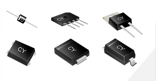
High Quality Rectifier Diode with Competitive Price, Fast Shipping, Order Now.Years of experience.
The company has domestic advanced diode production equipment, complete testing methods and quality assurance system.
Advanced Technology.Electronic component diodes are widely used in household appliances, green lighting, network communications, power chargers, automotive electronics and other fields.
Rectifier Diode,diode Bridge Rectifier,KBU Bridge Rectifiers,rectifier diode,Fast rectifier diode Changzhou Changyuan Electronic Co., Ltd. , https://www.cydiode.com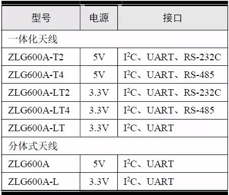





















Peripheral driver code writing skills for the card reader module
6.4 Read and write card module