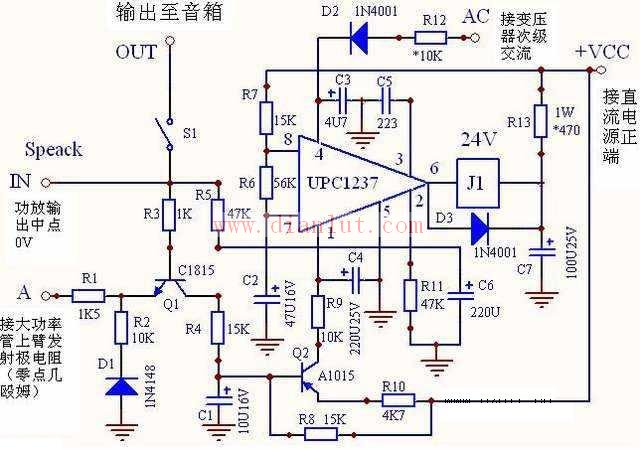
The following is a circuit diagram of [speaker protection circuit diagram based on uPC1237] The uPC1237 is powered by a single power supply and operates from a voltage range of 25v to 60v. It is usually powered directly from the positive power supply +Vcc of the power amplifier. The voltage of the relay coil is 24V DC, because the limit current of the 6-pin relay drive terminal is 80mA. When the relay is energized, the 6-pin voltage is about 0v. If the average Vcc voltage is >24v, the step-down current limiting resistor R12 must be connected. The relay and the integrated circuit are not damaged by overcurrent heating. The correspondence between the resistance and power consumption of R12 and the average voltage of Vcc is shown in Table 1. Fans can determine R12 according to Table 1 of their average vcc voltage value. The uPC12377 pin is the power-on delay terminal. The R7 and c3 parameters determine the power-on silence time. That is, after the power is turned on, when the power amplifier circuit reaches equilibrium and stability, the delay circuit allows the relay contact to turn on the speaker. This can completely eliminate the power-on shock noise, and increase the c3 or R7 to extend the power-on silence time. The uPC12378 pin is the power terminal, and the maximum limit is 8v. When Vcc is different, the resistance of R8 is different, which can be determined by Table 1. The uPC12374 pin is an AC power-off detection terminal, which is used to mute the power amplifier. When the power switch of the power amplifier is turned off, the secondary AC voltage of the transformer disappears immediately. The small capacity capacitor of c2 is quickly discharged by the internal resistance of the 4-pin. The voltage of the 4-pin is rapidly decreased. The internal circuit control relay acts to disconnect the output end of the power amplifier from the speaker. The current impact on the speaker when the zero level of the output of the power amplifier is out of balance during the transition after power failure (ie, the shutdown impact noise). The maximum limit voltage of 4 feet is 10v. When the AC voltage value of the secondary winding of the power amplifier power transformer is different, the value of the voltage limiting current limiting resistor R6 is different. If the voltage is too large or too small, the speaker protection circuit will not work normally. The relationship between Ac AC voltage and R6 resistance is shown in Table 2. The uPC12372 pin is the DC offset detection end of the output of the power amplifier. The DC offset voltage of the output of the power amplifier is too large, which will make the DC current flowing through the voice coil of the speaker too large, the dynamic range of the voice coil becomes smaller, the sound is distorted, and the voice coil is overheated. Very vulnerable. In order to protect the speaker, the DC level of the output of the power amplifier is monitored by the 2-pin. Once the positive or negative offset voltage of the amplifier output exceeds the set threshold, the internal circuit of the uPC1237 releases the relay, and the speaker is disconnected from the output of the power amplifier to protect the speaker. purpose. As shown in the figure, the positive offset threshold of the output of the circuit amplifier is 1.24v, and the negative offset is -1.04v. The uPC12371 pin is an overcurrent detection terminal. Left and right channel overcurrent detection L-E terminal, R-E terminal respectively connected to the discrete component power amplifier left and right channel final stage NPN amplifier tube emitter resistance, the voltage on the emitter resistor will rise due to the increase of output current. When the output average current exceeds the rated current value of the power amplifier or the speaker, the voltage on the emitter resistor reaches the overcurrent threshold voltage set by the speaker protection circuit, and T1, T3 or one of them is turned on, causing T2 to be turned on, and Vcc voltage After T2, R9, and R11 are added to 1 pin, as long as the current of pin 1 exceeds 110uA, the internal overcurrent protection circuit will release the relay and disconnect the speaker to achieve the purpose of speaker overcurrent protection. In the figure, the L-E, R-E over-current detection valve voltage is 0.67v. For the integrated circuit power amplifier, the emitter resistance of the final stage power amplifier tube is rarely taken out, and the overcurrent detection function can be omitted. It is only necessary to ground the 1 pin. The uPC12373 pin is the selection terminal for the speaker protection circuit. Ground the 3 feet directly to the automatic reset mode. That is, after the protection circuit is activated and the relay is disconnected from the speaker, if the power amplifier circuit returns to normal, the relay can automatically resume to turn on the speaker. Grounding the 3 pin through the 0.022uF capacitor is the latching mode. That is, once the relay is disconnected from the speaker, even if the power amplifier circuit returns to normal, the relay will remain in the off state until the power switch is turned off once and then turned on again. Regardless of the mode of operation, the speaker protection circuit function is unchanged, and the uPC1237 parameters mentioned in the figure and in this paper are all latched.
Red IDC Connector:IDC connector Automotive Connector is a kind of component that electronic engineering and technical personnel often contact. Its function is very simple: in the circuit is blocked or isolated between the circuit, set up a bridge of communication, so that the current flow, so that the circuit to achieve the intended function. The form and structure of automobile connector are changeable. It is mainly composed of four basic structural components: contact, shell (depending on the variety) and insulator. Red IDC Connector ShenZhen Antenk Electronics Co,Ltd , https://www.coincellholder.com
